LoRa SX1262 vs LR1121 for 868Mhz
LoRa SX1262 vs LR1121
The original SX127X series of UHF LoRa devices was improved when the SX126x series was launched and now we have the further improved LR11xx series.
The LR11xx modules have become popular for use in Meshtastic at 868Mhz and according to the data sheet do offer slightly improved sensitivity for an already long range LoRa technology.
I was interested in seeing if the improvements suggested in the data sheet were matched with real application improvements.
I had already produced some link test programs using RadioLib which is the LoRa library used by Meshtastic, see here;
https://stuartsprojects.github.io/2025/10/01/LoRa-Testing-for-868Mhz.html
Whilst those programs were adequate for testing antennas they were not really suitable for checking receiver sensitivity and similar.
You might assume that the LoRa devices reported RSSI and SNR would give some indication of sensitivity, but the values that indicate actual impending link failure can vary between different device types.
It would be possible to arrange a series of remote transmitters that would send packets from 50km, 60km and 70km etc. If a particular receiver picked up packets from a further distant transmitter that would represent an improvement in sensitivity. However that is a difficult testing scenario to arrange in practice.
Rather than changing the distance from transmitter to receiver we can simulate different distances by changing the transmit power. If receiver A can pick up packets transmitted at 10dBm and no lower power but receiver B can pick up 9dbm, 8dbm and 7dbm power packets, receiver B has a 3dBm greater sensitivity. This greater sensitivity will mean that receiver B can also receive packets from a greater distance than receiver A.
Its easy to arrange for the transmitted packet to contain the value of transmit power that was used to send it. The receiver can then decode the packet and record the powers that were used to send the packets it receives.
3_LoRa_Link_Test_Transmitter and 4_LoRa_Link_Test_Receiver Programs
I modified the 1_Basic_LoRa_Transmitter 2_Basic_LoRa_Receiver programs so that instead of using a fixed power level for the transmission the packets were sent at reducing power levels in a loop. with definable start and finish powers. For example you might choose to send packets at powers from 20dBm down to -9dBm. _9dBm is the lower power limit of a SX126X and LR1121.
So the transmitter would send a series of packets;
20dBm 19dBm 18dBm . to . -8dBm -9dBm
The packet sent is in ASCII and contains the power level used to send it and looks like this;
Link+20 Link+19 Link+18 . to . Link-08 Link-09
The loop starts at 20dbm go down to -9dBm in 1dBm steps then start again at 20dBm. At the start of the loop a packet of format ‘Link999’ is sent which the receiver recognises as the start of the loop.
The receiver decodes each received packet and stores the number of each power level received in an array. When the ‘Link999’ packet is received the receiver prints out, to the Serial monitor and\or SD card log, the totals of each power level received, 22dBm to -9dBm, like this;
22dBm,17  21dBm,17  20dBm,17  19dBm,17  18dBm,17  17dBm,17  16dBm,17  15dBm,17  14dBm,17  13dBm,16  12dBm,16  11dBm,16  10dBm,17  9dBm,17  8dBm,15  7dBm,15  6dBm,12  5dBm,5  4dBm,4  3dBm,1  2dBm,0  1dBm,0  0dBm,1  -1dBm,0  -2dBm,0  -3dBm,0  -4dBm,0  -5dBm,0  -6dBm,0  -7dBm,0  -8dBm,0  -9dBm,0
CSV,17,17,17,17,17,17,17,17,17,16,16,16,17,17,15,15,12,5,4,1,0,0,1,0,0,0,0,0,0,0,0,0
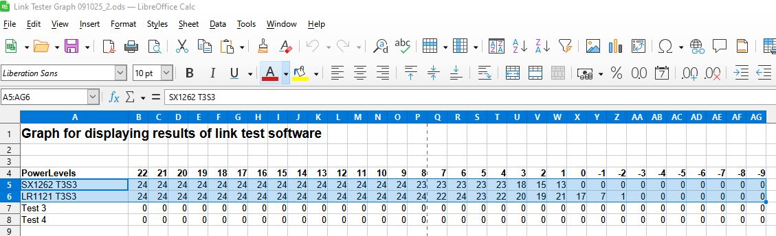
Now the CSV line can be cut and pasted into a text file, Windows Notepad will do, then saved as a file with a .CSV extension. This CSV file can then be opened with a spreadsheet program, I use LibreOffice. The data from the CSV file can then be copied into a spreadsheet, ‘Link Tester Graph’ that will display the pasted data as a Graph.
Practical Link Test Example - SX1262 versus LR1121
So I programmed the Link test receiver program into an SX1262 Lilygo T3S3 and a LR1121 Lilygo T3S3. I programmed another T3S3 with the link test transmitter software. I used a frequency of 868Mhz, a bandwidth of 250Khz and a spreading factor of 11, these are the Long Fast settings in Meshtastic.
I placed the SX1262 T3S3 receiver on my portable table at my local playing field.
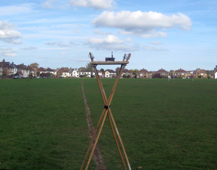
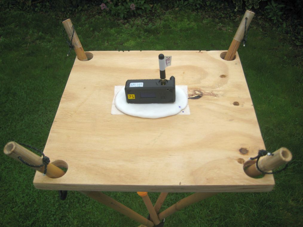
The T3S3 receiver sits a plastic base made from the hot melt plastic that makes the T3S3 stay in exactly the same place for each test. The ‘table’ is also stable and does not move around. The same antenna was used for the SX1262 and LR1121 versions of the T3S3.
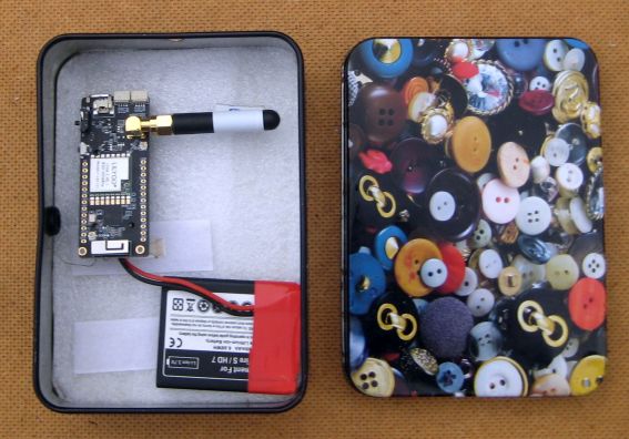
The transmitter was another T3S3 placed in a metal tin (lid on) to significantly reduce the radiated power level, of all packets, and thus simulate a transmitter that was maybe 150km away. This transmitter was located away from the receiver that was on the table. The distance was adjusted so that the packets down to circa 0dBm were being received, with the -1dBm to -9dBm packets not being received. The spacing distance was about 100M away.
Both the SX1262 and the LR1121 were then placed on the table in turn, switched on and the packets received then logged to a file on an SD card. Each test was run for about 5 minutes.
The principle requirement of the test was that as far as possible nothing changed between the different receiver tests, the transmitter and receiver were in the exact same position, the antenna was the same, there were no people nearby potentially disturbing reception, all that changed between the tests was that one test was with and SX1262 receiver and the other was with an LR1121 receiver.
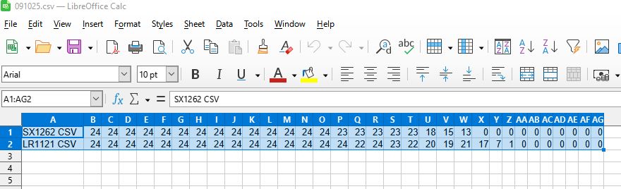
I then extracted the results of the tests from the logs on the SD card, posted them into Notepad and saved the file as a CSV;
SX1262 CSV,24,24,24,24,24,24,24,24,24,24,24,24,24,24,23,23,23,23,23,18,15,13,0,0,0,0,0,0,0,0,0,0
LR1121 CSV,24,24,24,24,24,24,24,24,24,24,24,24,24,24,24,22,24,23,22,20,19,21,17,7,1,0,0,0,0,0,0,0
I opened the Graph generator, ‘Link Tester Graph’ then opened the Log CSV file in my spreadsheet program selected the block of data and copied it;
And next pasted it into the data area in the ‘Link Tester Graph’ spreadsheet;
The graph of the test data looks like this;
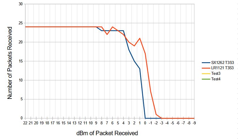
If you look at the gap in the two plots at the point where circa only 50% of the packets were received you will see that the SX1262 (blue plot) is receiving down to 1dBm but the LR1121 (red plot) is receiving down to -0.5dBm, which indicates around a 1.5dBm gain in sensitivity.
LR1121 wins by 1.5dBm !
So the LR1121 shows a gain improvement of 1.5dBm over the older technology SX1262. This increase in sensitivity would improve distance reception by approximately 20%.
Files
The program files described above and the Graph spreadsheet can be found here;
https://github.com/StuartsProjects/Devices/tree/master/RadioLibLoRaTestPrograms
Important Note
The programs described here were for the Lilygo T3-S3 which uses a ESP32S3 which has 4Mb of flash memory. The programs use the RadioLib library and even simple TX and RX program wont fit in an Arduino such as a UNO or Pro Mini since the memory the programs need exceeds what is available on these Arduinos. Also note that the program compile times with the RadioLib library can be several minutes.