LoRa Testing for 868Mhz
Simple Testing of 868Mhz Boards and Antennas
I was interested in giving Meshtastic a try, it uses LoRa after all.
In the UK Meshtastic is used on the 868Mhz band and I already had a few of the Lilygo T3-S3 868Mhz boards which are supported for Meshtastic. I was also interested in testing the newest LoRa device, the LR1121 to see if there was any sensitivity differences between that and the older SX127X and SX126X LoRa devices, there is a LR1121 version of the T3-S3.
A lot of testing for LoRa devices, antennas, receiver differences or power supply performance can be done using simple transmitter and receiver programs. For instance if you set-up a transmitter and receiver in a controlled environment you can easily compare the performance of different antennas by observing, recording and comparing the RSSI of the received packets when you change between antennas.
I got some 3D printed cases for the Lilygo T3-S3 boards so the T3-S3 board could have an attached battery and would stand in a stable and fixed location.
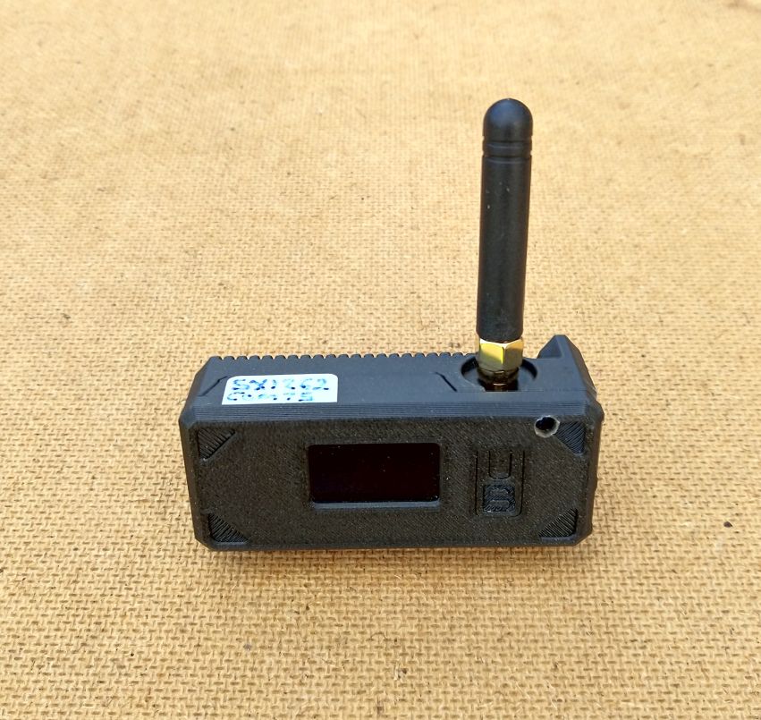
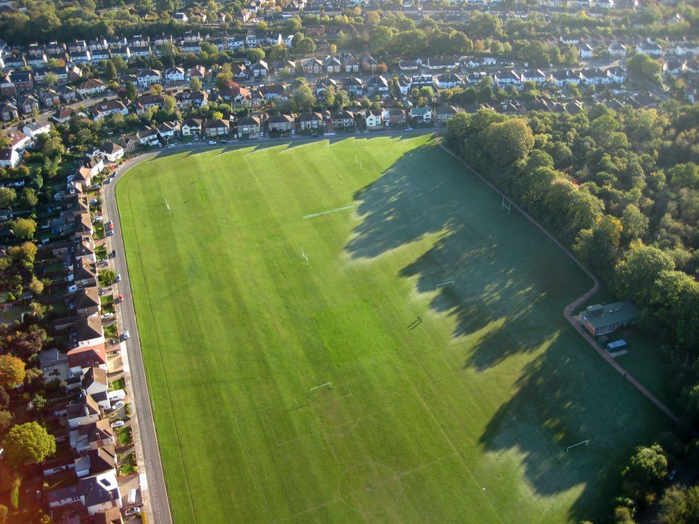
For the controlled, and repeatable test environment, I went of course to my local playing field.
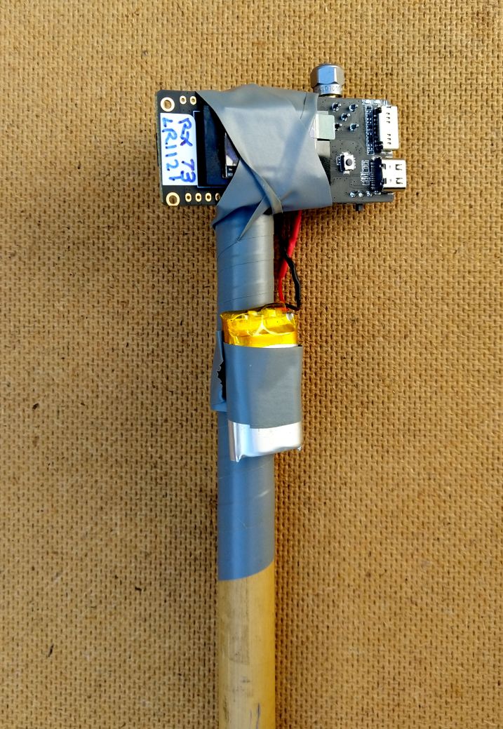
The transmitter can be another T3-S3 board and battery taped to a single bamboo pole pushed into the ground. Note that in this case that in place of the antenna an SMA terminator has been fitted, more on this later.
To place the receiver I have an easy to erect table that is a simple square of plywood with holes in the corners. Four bamboo poles are tied together and it easily erects into a small stable table where a receiver can be placed. You can stand well back whilst the receiver is doing its receiving and there is no nearby metal. The receiver program displays the packet RSSI and SNR on the OLED and will optionally record the same data to an SD card plugged into the T3-S3 or report over a Bluetooth connection to an Android phone.
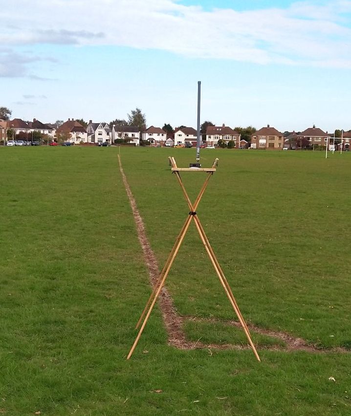
The SD card and Bluetooth reporting options are useful since it can be difficult to read the small OLED when its sunny outside. Android Mobile phones using the Bluetooth connection are in general quite readable outdoors and you can have large text too.
To test an antenna you remove the receiver T3-S3 from the table and fit the antenna. Then switch on the T3-S3 and the OLED will show you the name of the SD Log file where the reception results are recorded. You could just read the results from the OLED and\or Bluetooth, but it is easier to analyse the results later from the log file on the SD card.
Programs
I was using the Arduino RadioLib library since this library supports the newer LR1121 LoRa device.
Meshtastic also uses the RadioLib library which provides support for a range of radio modules including the SX127X, SX126X and LR1121 LoRa modules so comparisons could be done using the same library for the different LoRa modules.
I wanted some simple transmit and receive examples so I started with the the basic examples provided in the RadioLib library;
https://github.com/jgromes/RadioLib
and added some modifications to make the settings easy to change, add serial print, display and SD logging routines. The resulting Arduino sketches can be found here;
https://github.com/StuartsProjects/Devices/tree/master/RadioLibLoRaTestPrograms
1_Basic_LoRa_\Transmitter and 2_Basic_LoRa_Receiver programs
Within the programs the LoRa frequency and modem settings are entered in the Settings.h file which makes changing LoRa parameters very easy. The settings below are those used for testing these antennas. They are the Meshtastic Long Fast settings, with a slightly different frequency used to avoid potential problems with any nearby Meshtastic devices.
Frequency = 868.0Mhz
Bandwidth = 250Khz
SpreadingFactor = 11
CodeRate = 5 (4:5)
SyncWord = 0x2B
TXpower = 10
PreambleLength = 16
Also within the Settings.h file the various options for the examples can be configured by ‘commenting in’ the #includes. For example if the Settings.h file is edited so that it looks like this;
#define PRINT_ASCII      //enable to print ASCII of packet
//#define PRINT_HEX      //enable to print HEX of packet
#define USE_DISPLAY      //enable OLED
#define USE_SD           //enable SD card for logging
//#define USE_BLUETOOTH  //Requires an ESP32 processor and version 3.0.0 and above of Expressiff ESP32 Core for IDE.
//#define USE_BUZZER     //on GPIO10, pin 3 of P3, connector nearest long edge of board, receiver only
And you then configure for the selected LoRa device by editing an included file called Lilygo_T3S3.h which contains the pin definitions used by the LoRa device and the type of LoRa device also, see below;
//#define USE_LR1121     //enable this define if using an LR1121 LoRa device
#define USE_SX1262       //enable this define if using an SX1262 LoRa device
With the above settings the program will compile for the SX1262 and use the OLED and the SD card for logging. The packets received will be printed in ASCII on the serial monitor and OLED, with no HEX printing and Bluetooth output is not enabled.
Test distances
To test the antennas I wanted them to be receiving weak packets as if the transmitter was many kilometres from the receiver.
Meshtastic normally uses the full available power on the SX1262\LR1121 of 22dBm. However the transmit power can be set to as low as -9dBm, so 31dBm lower.
If you look at the picture of the T3-S3 taped to a bamboo pole above, the antenna has been replaced by an SMA terminator. The terminator provides a good impedance match but also significantly reduces the amount of radiated RF power from the LoRa transmitter. This reduction is about 30dBm.
If we then combine reducing the LoRa module transmit power to -9dBm and replacing the antenna with an SMA terminator the amount of radiated power is about 60dBm less that a standard Meshtastic node and antenna set-up.
A power increase of 20dBm is a power increase of 100 times and a distance increase of 10 times. The total 60dBm cut in radiated power is 3 lots of 20dBm and thus a range\distance difference of 10 x 10 x 10 = 1000. So if we reduce the radiated power by this 60dBm and place the transmitter 50M from the receiver the receiver will see signals at a level that would be expected from a Meshtastic node 50M x 1000 = 50KM away. So 50M on a playing field behaves like a 50KM test range, that ought to be realistic enough.
Between antenna changes I switched the receiver off\on so that I got a different SD log file name for each antenna. When the T3_S3 is switched on one of the messages printed on the OLED is the name of the SD log file being used. Thus I could easily review the test results when back in the workshop.
An example of the SD log file output is below. The log file is saved in CSV format so can be directly loaded into a spreadsheet program.
Selected device SX1262
Frequency 868.000000
Bandwidth 250.0
SpreadingFactor 11
CodeRate 4: 5
Syncword 0x5
TXpower 10
CurrentLimit 140
PreambleLength 16
LoRa00270,RXBytes,10,RSSI,-107,SNR,2.50,RXOK,1,Errors,0
LoRa00272,RXBytes,10,RSSI,-108,SNR,1.25,RXOK,2,Errors,0
LoRa00273,RXBytes,10,RSSI,-108,SNR,1.00,RXOK,3,Errors,0
LoRa00274,RXBytes,10,RSSI,-108,SNR,1.00,RXOK,4,Errors,0
LoRa00275,RXBytes,10,RSSI,-109,SNR,0.25,RXOK,5,Errors,0
To analyse the results, first I deleted the configuration information at the file start and then deleted all but the 50 results in the middle. I had run each test for circa 60 seconds so there were around 100 results total in the log. All you need to do then is select the RSSI values column, do a sum of the values and divide by 50, to give an average RSSI.
Antennas
Here are the antennas I tested, labelled A to G.
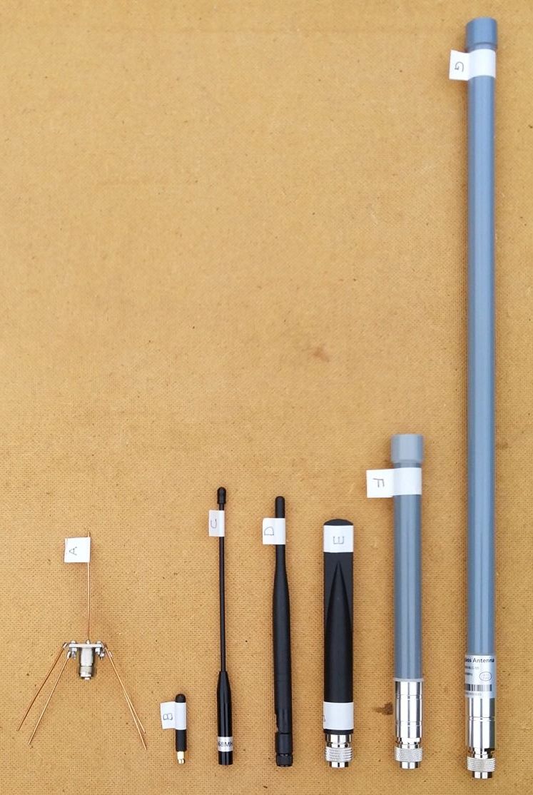
A is a DIY 1\4 wave vertical with four 1\4 wave radials, it’s easy to make and serves as a good reference antenna, here are the parts needed;
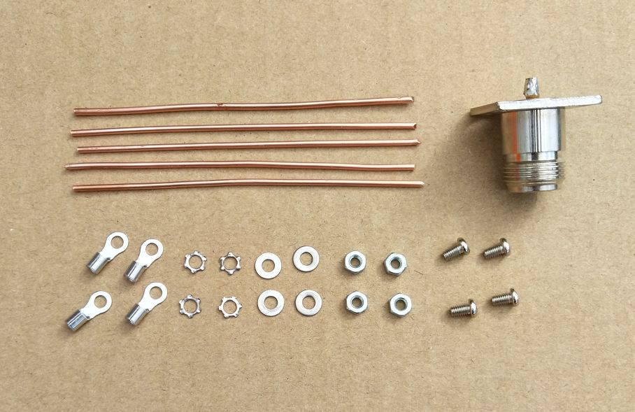
Crimp and solder the tags to the end of the 4 radials and fit with short M3 screws and nuts to the 4 mount holes in the chassis N-Type socket. Solder the fifth wire to the centre pin on the chassis socket. You will need an N-Type pug to SMA adapter to fit this antenna to the T3-S3.
Antenna test results
Average RSSI
A -106.7dBm
B -109.1dBm
C -103.0dBm
D -101.6dBm
E -101.2dBm
F -107.1dBm
G -98.7dBm
SWR tests at 868Mhz, measured with a N1201SA RF vector Impedance Analyzer
A 1.44
B 3.28
C 1.52
D 1.23
E 1.3
F 2.34
G 1.32
So in RSSI reception terms the antennas performance in order was, best to worst;
G, E, D, C, A, F, B
And in SWR terms the antennas in order were, best to worst;
D, E, G, A, C, F, B
The best antenna, providing the strongest signals was antenna G the very large one (55cm long!), the worst was antenna B the short stubby one supplied with the T3-S3. The difference between the worst and best was circa 10dBm, so the little stubby antenna would only have about 1\3rd the range\distance of G the best antenna.
Antenna B is the short stubby thing that comes with the T3-S3 boards and you would not expect them to be very good, so no surprise with the test results. Antenna F (23cm long) was only a little better, that was a surprise.
Note that whilst the SWR gives a clue as to how effective an antenna might be performance wise, you cannot use SWR directly to select good vs bad antennas.
Antenna F looks suspicious, poor RSSI and poor SWR, such are the benefits of purchasing stuff from the large far East market places. It did have a similar SWR at 2.5Ghz, so maybe it was actually some type of multi band antenna, that was just poor in all bands.
The testing and comparison of the 7 antennas took about 30 minutes.
Packet delays
Appreciate that the receiver program, on receipt of a packet, can spend a fair bit of time printing the details of the packet, displaying them on the OLED, sending to Bluetooth and logging to the SD card. Thus do not attempt to use very short delays between packet transmissions, the receiver can miss packets because its busy processing the last received packet.
Important Note
The programs described here were for the Lilygo T3-S3 which uses a ESP32S3 which has 4Mb of flash memory. The programs use the RadioLib library and even simple TX and RX program wont fit in an Arduino such as a UNO or Pro Mini since the memory the programs need exceeds what is available on these Arduinos. Also note that the program compile times with the RadioLib library can be several minutes.