Improving LoRa Reception - Part 1
Introduction
Whilst this post is specifically about using a PA (transmitter power amplifier) and LNA (low noise receiver amplifier) to improve or extend LoRa reception it does also describe a very simple method that can be used to accurately test and measure the improvements that can be made in LoRa reception by using amplifiers or different types of antennas.
Improving reception
LoRa is a long range method of radio communication, but there still may be circumstances where you want to improve reception distances. High gain antennas are one way to do this but legal restrictions on effective radiated power (ERP) often require you to reduce transmit power when using directional antennas that have gain. The reduction in power can completely negate the distance benefits of using a gain antenna in the first place, in other words using a gain antenna can be of no benefit.
There are plenty of LoRa modules out there that attach an RF power amplifier to the LoRa devices output and that can increase the distance at which the LoRa packets are then received but quite often the extra transmit power is not legal.
So how can you improve reception range, could you perhaps somehow amplify the very weak incoming LoRa signals from the remote transmitter ?
There are many RF amplifiers for receivers but LoRa typically operates well below the local RF noise level. Amplifying RF is in itself easy enough but doing so also tends to increase the amount of RF noise present as well so although the wanted signal level is increased the noise level rises too. To improve LoRa reception you would need to increase the wanted RF signal level but keep the added noise level very low. So a special type of low noise amplifier (LNA) is needed.
Some years back (2018) I did test some specialised LNAs;
https://stuartsprojects.github.io/2018/01/09/can-we-improve-LoRa-performance.html
One of the amplifiers used was the G4DDK bought as a kit for around £55. That improved reception by 4dBm at SF7 and 3.5dBm at SF12. The SP7000 LNA improved reception by 5dBm at SF7 and 7dBm at SF12. The SP7000 LNA is a specialised LNA primarily for 70cm (434Mhz) HAM use and costs circa £350. Both these LNAs were used with LoRa in receive only mode.
So I was interested to see an amplifier advertised for LoRa at low cost, circa £25, that claimed to automatically switch between using an LNA for receive and a power amplifier for transmit with a 11dBm transmit power gain. This is the AB-IOT-433;

I was not interested in the RF power amplifier bit since I do want my devices to keep to legal limits. That the module can automatically switch between RX and TX modes is useful and needs no additional GPIO pins or software to control the switching. The AB-IOT-433 quotes a receive gain of 11dB±2dB and you would expect that level of gain to increase reception distance by a factor of maybe 4 times.
So how do we check how the device actually performs ? You might get an indication if when you use it in an application you pick up LoRa nodes from further away, but thats a bit vague.
One way of checking or measuring the gain would be to put a LoRa transmitter and receiver in an RF anechoic chamber and carry out a range of controlled tests all out of the way of external influences. For most all people that’s just not practical.
Of interest is not really how much the AB-IOT-433 improves reception in a laboratory environment but how good is it in real world tests.
Simplify Range or Distance Tests
What we can do is simply record the distance at which reception of LoRa packets stops, first without using the AB-IOT-433 and then compare with the AB-IOT-433 in use. Some thought is needed about simplifying the test process as LoRa reception can easily be several kilometres.
If you were to carry out outdoor range and distance tests, say in a typical flat urban area with normally set-up nodes then you might well need a very large area indeed. To make tests practical in an area as small as a football pitch we need to significantly reduce the radiated power of the transmitter.
Lets imagine we can get the transmit power so low that the distance where reception stops is 50M away from the transmitter. If we were then somehow able to amplify or improve the received signal with a better antenna or an LNA by say 6dBm, we would expect the receiver to now pick up the LoRa at twice the distance from the transmitter i.e. 100M. Thus if in the real world application we used the same antenna or LNA improvements then we should also double the reception distance.
So in order to evaluate the performance of the AB-IOT-433 PA and LNA I decided to use a Lilygo T-Beam with SX1262 LoRa device as the transmitter and an LilyGo T3 V1.6.1 SX1278 as the receiver. The T-Beam with SX1262 is a good choice for the transmitter as the transmit power can be reduced down to -9dBm where as the lowest the SX1278 will normally go is 2dBm. Thus in practical terms the range of the SX1262 transmitter can be cut to around 1/4 of the distance of the SX1278.
However, even at -9dBm, LoRa packets could have long range and so a large test area would still be needed. We need to reduce the emitted power level even further.
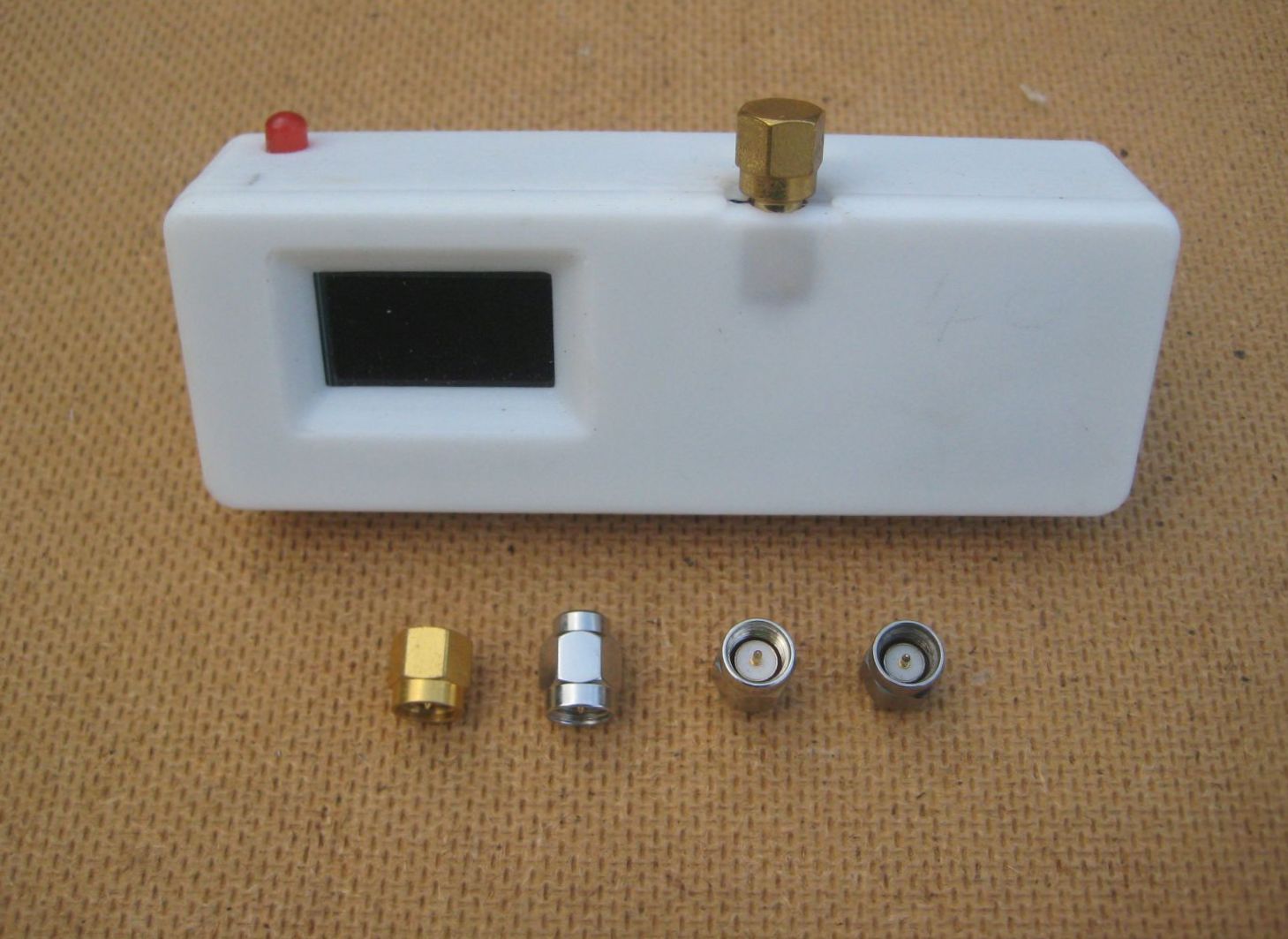
Replacing the LoRa transmitters antenna with a SMA terminator can massively reduce the range of the LoRa packets as most all of the RF power is dissipated in the resistor of the SMA terminator.
Some SMA terminators are shown below, with one fitted to the T-beam, all the terminators are 50ohm and can screw in in place of the LoRa devices antenna.
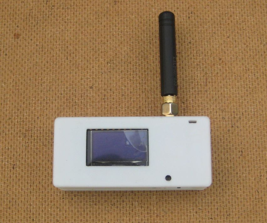
For the receiver I would use an LilyGo T3 V1.6.1 SX1278;
For the test area, then somewhere clear of obstructions and far from possible reflecting things like buildings is a good idea. A quiet area over one of my the local parks is ideal. Before I went to the park I did some simple checks in the street outside my house to see how short I could easily cut the range\distance too.
With the T-Beams antenna replaced by an SMA terminator and the transmitter fixed to a bamboo pole pushed into a bit of grass, I loaded the transmitter and receiver up with the simple test programs from a previous set of tests;
The transmitter and receiver were set to SF11 and bandwidth 250khz which are the settings used by the Meshtastic ‘Long Range Fast’. The transmitter sends a LoRa packet once a second and if the receiver picks up the packet it flashes an LED, sounds a buzzer (if fitted) and displays the RSSI, SNR and packet count on the OLED display.
The test process is very simple, you stand next to the transmitter (the T-Beam) holding the receiver (the LilyGo T3 V1.6.1 SX1278) in one hand with arm out stretched at shoulder height and facing the transmitter. You want there to be a direct path from transmitter to receiver. Then you walk away from the transmitter until the receiver no longer receives packets, the beeps will stop, the LED flashes will stop and the OLED will not show new packets.
For this test, out in the street, I stopped receiving packets at circa 20M with no AB-IOT-433 fitted. So the transmitted power has been cut enough to limit the reception distance to 20M, thus testing over the local park looks practical. So I wait for a nice day and go over the local park.
Note that absolute distance measurements are not needed, all we are doing is measuring the difference in distances between tests. Sure you can use a long tape measure if you want, but simple consistent step counting is perfectly adequate. What is important is the keep the position and height above ground of the transmitter and receiver antennas the same so comparisons between tests are valid.
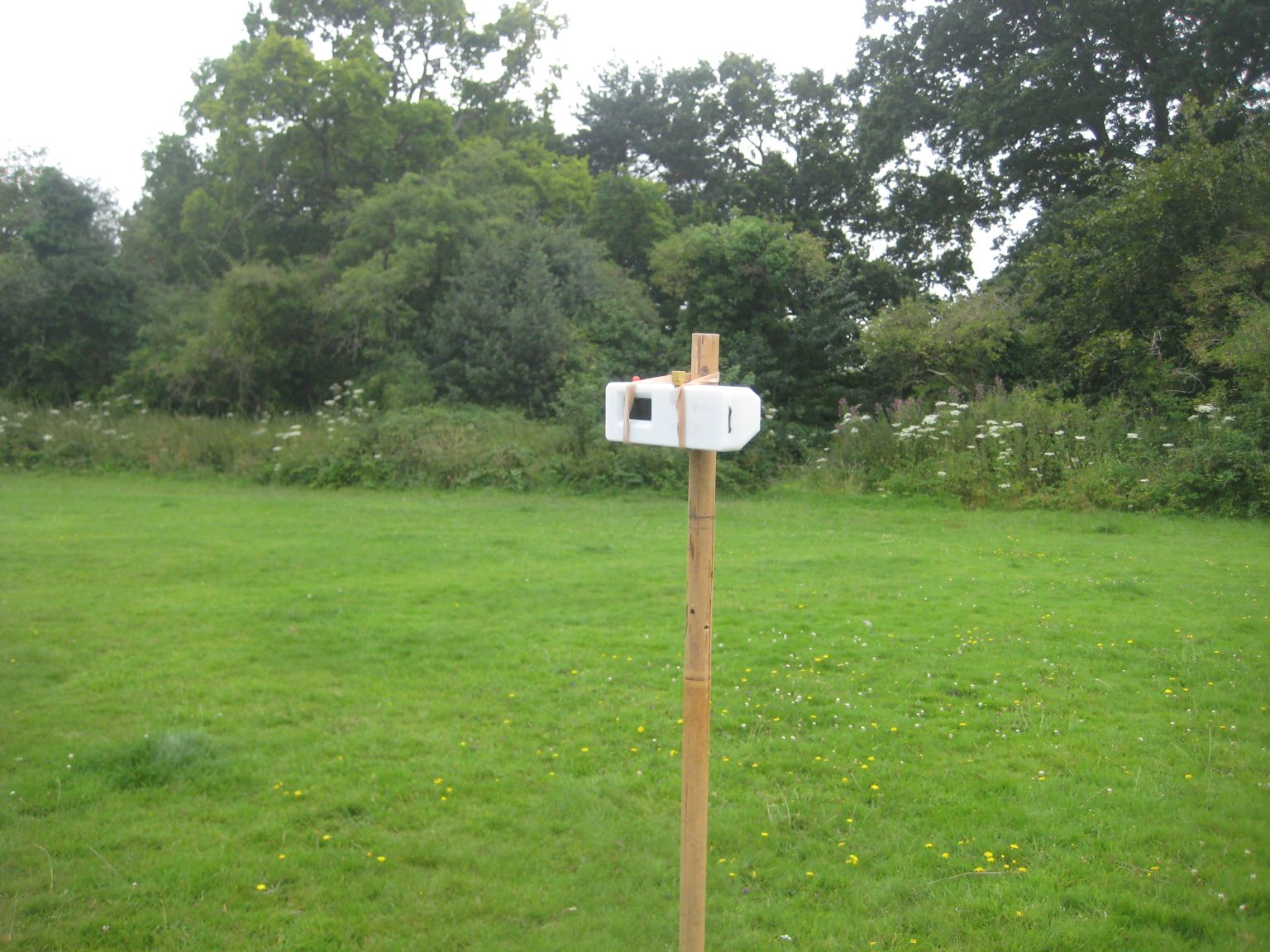
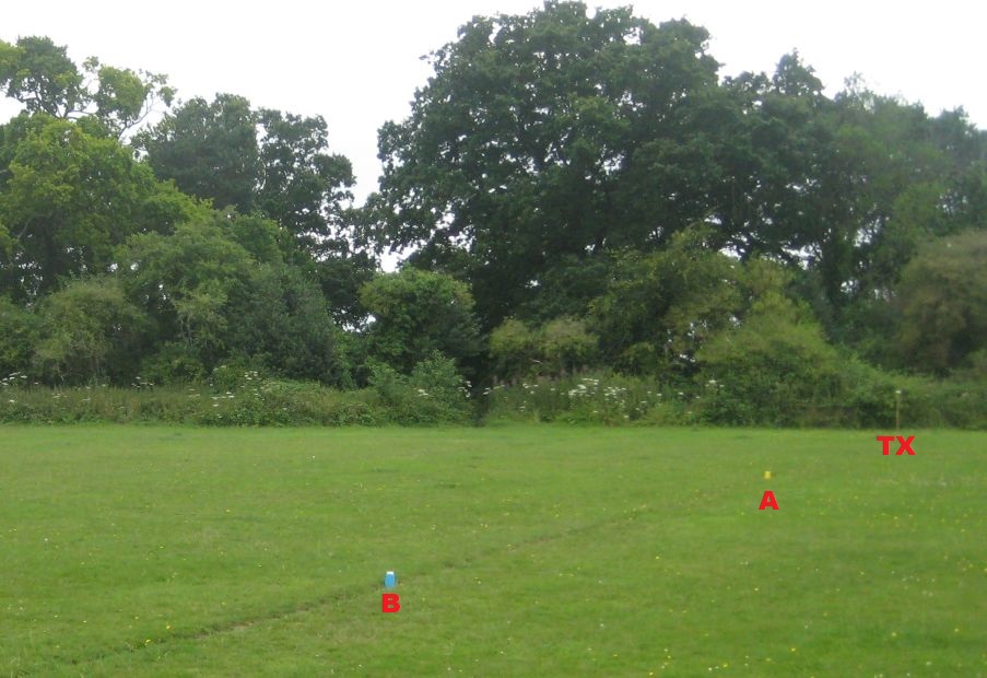
Here is the transmitter, with SMA terminator replacing the antenna, on a bamboo pole in the corner of a football pitch.
With a standard stubby type antenna on the LilyGo T3 V1.6.1 SX1278 packet reception stops at 20M.
I then fitted the AB-IOT-433 LNA\PA as so;
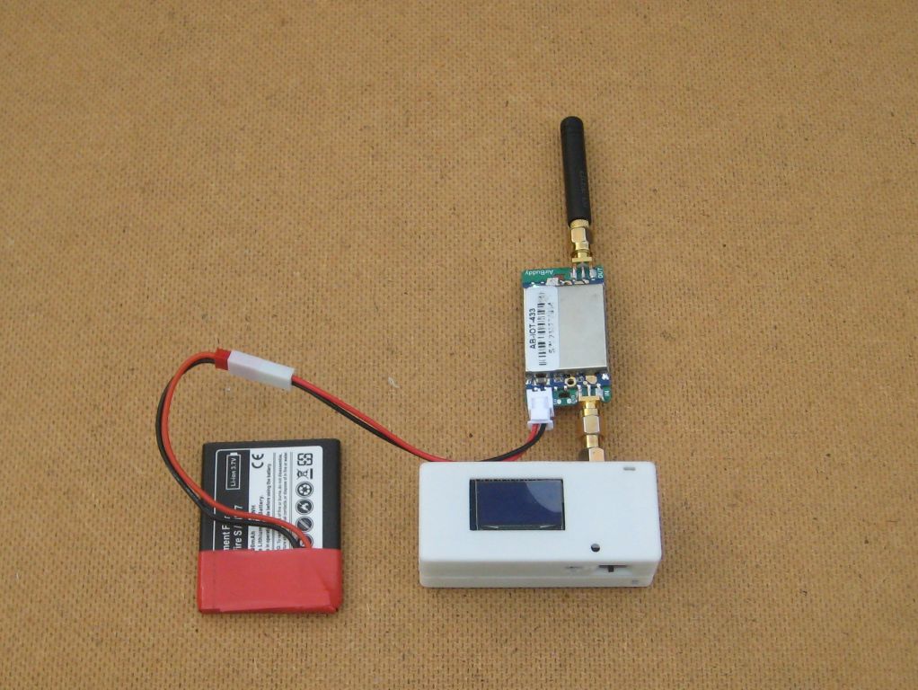
And repeat the test. Reception now stops at 38M. So in approximate terms the LNA in the AB-IOT-433 doubles the reception range.
Below is the view of my outdoor anechoic test chamber, the T-Beam transmitter is marked with TX, the yellow cup at A marks the location where the AB-IOT-433 was not used in line with the antenna. The Blue cup at B marks the place where reception stopped with the AB-IOT-433 fitted in-line with the antenna.
Measuring the RF output power of the AB-IOT-433
The amplifier quotes an RF power amplifier gain of 5-11dBm that is adjustable via a small pre-set.
Using the set-up below I first checked the transmit power of the LoRa node and then the range of power output with the AB-IOT-433 in place.
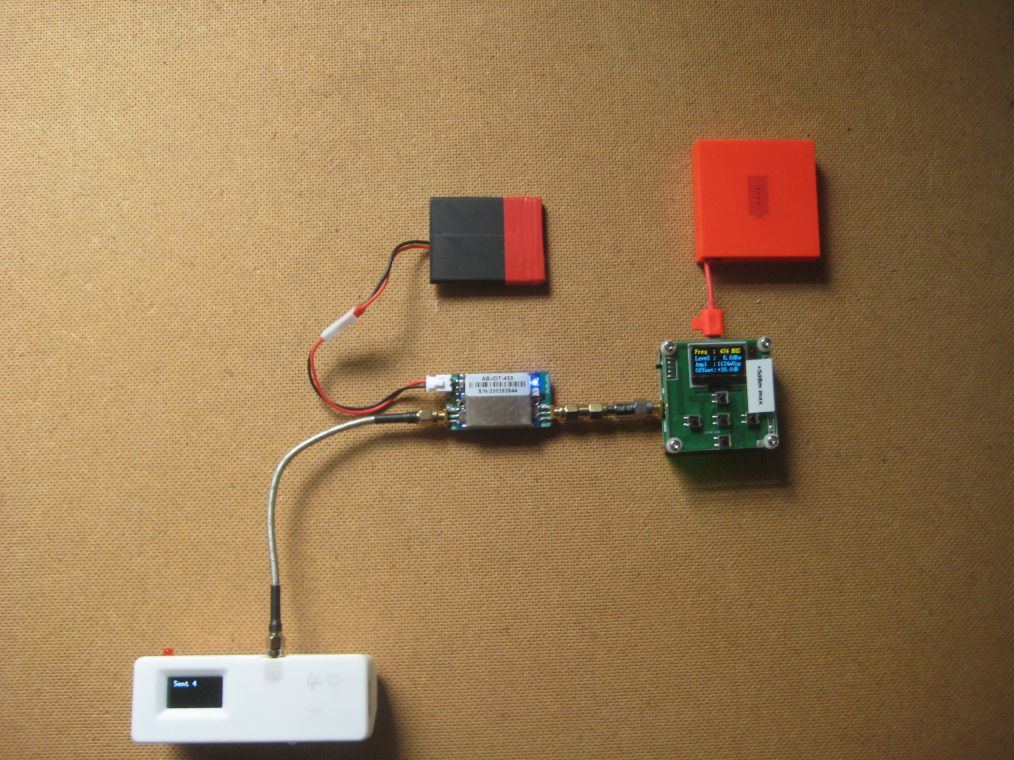
The RF power amplifier in the setup above has a 30dBm attenuator added in line with the antenna lead and this is programmed into the RF power meter as an offset so that there is a direct read out in dBm. The power meter has a max power input limit of 5dBm.
I programmed up the LoRa node to transmit a packet that was around 5 seconds long, this gives plenty of time for the meter to stabilise.
LoRa RF output power 2dBm, AB-IOT-433 minimum setting 7.6dBm, AB-IOT-433 maximim setting 14.6dBm
LoRa RF output power 10dBm, AB-IOT-433 minimum setting 15.7dBm, AB-IOT-433 maximim setting 22dBm
LoRa RF output power 20dBm, AB-IOT-433 minimum setting 26.7dBm. AB-IOT-433 maximim setting 28.1dBm
So the RF power gain of about 10dBm seems OK.
AB-IOT-433 RF Power amplifier RX and TX Switching
The AB-IOT-433 is supposed to have an RF power amplifier and it should switch it in and out automatically, but does it do so fast enough to avoid corrupting a packet ?
I had written some Data Transfer software for sending and receiving files and images over LoRa. The process is that each part of the image\file is transmitted and the receiver replies with an acknowledgement that the transmitter is waiting for before sending the next segment. So the transmitter is repeatedly switching fairly rapidly between transmit and receive mode so the AB-IOT-433 has to automatically switch too. This does seem to work, no problems were encountered with the file\image transfers when the AB-IOT-433 was in place on the transmitter.
Summary
The AB-IOT-433 is small and easy to set-up. It offers an approximate doubling of range in LoRa receive mode. There is up to 10dBm extra transmit power available too. Would be useful to build it into a box with an internal battery to use as a portable ‘range’ extender.
Other testing
As you will have seen once you have a means of reducing the transmitted power significantly you have an easy way of doing real world performance comparisons of different receivers, set-ups and antennas.
Its quick and easy to do a range check with one antenna and then quickly swap antennas to see if there is a performance difference between them.
So I popped over the local park again and put the T-Beam with its SMA terminator in place of the antenna. This time I had set the transmit power to 2dBm, which is the lowest power for an SX1278. Thus if anyone anywhere in the World were to replicate the test, with the same transmitter (T-Beam) and reciever (LilyGo T3 V1.6.1 SX1278) the results should be similar, open spaces like parks don’t vary much propagation wise.
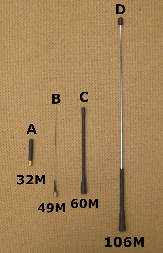
I tested 4 antennas, A,B,C,D. The first was a classic stubby which is a helical coil covered in rubber. The range for that was 32M. Antenna B was a simple DIY 1\4 wave wire, that had a range of 49M. Next was C, a rubber thing I found in my box of antennas, that had a range of 60M. Last was antenna D, a telescopic antenna that collapses to length that is smaller than antenna C, but when extended as shown it had a range of 106M.
So depending on the antenna, the best had a range that was 3.3 times the worst. So a worthwhile and simple test to carry out.
Next
How to carry out antenna performance checks on your bench.