Can we improve LoRa® device performance ?
Can we improve LoRa® performance is a question I have seen asked a few times. If we add additional bandpass filters or low noise amplifiers to a LoRa® installation, will it improve performance and range ?
A bandpass filter should limit the amount of external noise coming into the LoRa® devices antenna input. A lot of noise could de-sensitise the LoRa® receiver. I operate mainly at 434Mhz and there is a bandpass filter made for this frequency. It has a stated performance of;
NMRF FBP-433s
Centre frequency: 433.92 MHz
Pass band: 431.92 ~ 435.92 MHz
Insertion loss: < @431.92 1.5dB ~ 435.92 MHz
I needed to check this, so lacking a proper signal generator I programmed a LoRa® device to scan the frequency band and put the bandpass filter on the input of my RF Explorer.
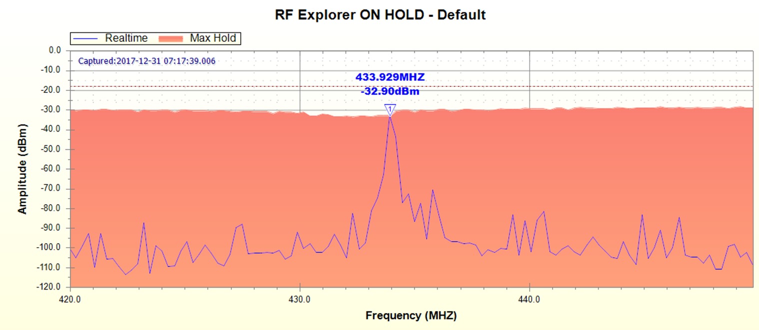
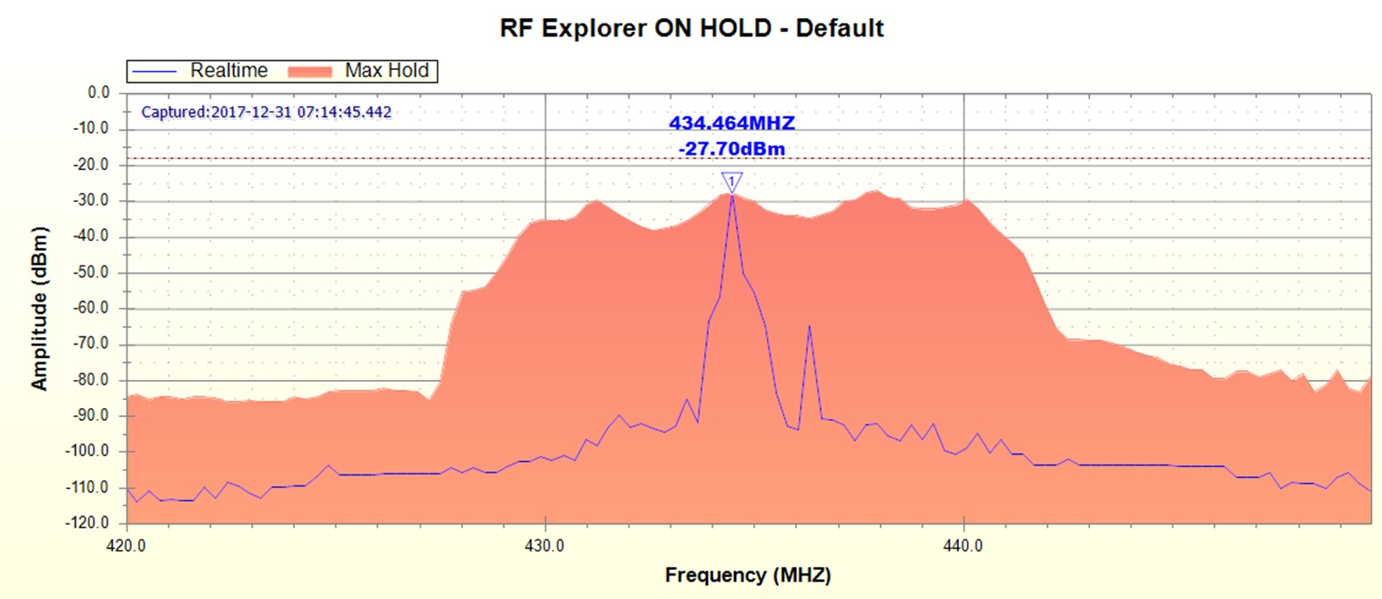
This was the output, first without the filter and then with.
 ]
]

Outside of 427Mhz to 443Mhz the attenuation was around 45dB, which should be good enough to get an idea as to whether a bandpass filter would improve LoRa® reception, the insertion loss of 1.5dB looked about right too.
You might be inclined to measure the effects of bandpass filters or low noise amplifiers in a laboratory, but I am more interested in what happens in the real world. So we need a practical testing method to use in the real outdoors.
A LoRa® transmitter can be programmed to send packets at power levels from 17dBm to 2dBm. If we send a series of packets that start at say 17dBm and then reduce by 1dBm all the way down to 2dBm, we can use these packets to measure the real world performance of the link.
Imagine we have a working link and all packets from 17dBm down to 10dBm are received. The packets sent at 9dBm and below are too weak to be received. We then change something in the link, a better antenna (TX or RX), add a bandpass filter or a low noise amplifier (LNA) and then run the same test over the same link. Imagine that after such a change we are receiving all the packets down to 5dBm. Whatever change we made has improved the link by 5dB.
We have established this 5dB improvement with no actual test measurement equipment, we used just standard antennas and simple LoRa® transmitters and receivers. You do need to run this type of test over a large number of iterations but all that needs is patience.
I wrote the required link test software for Arduino, and you can use it any of my tracker or receiver boards. The LoRa® parameters of bandwidth, spreading factor and code rate are all configurable as is the frequency. You use the same settings for transmitter and receiver of course. The transmitted packets contain the power level used to send them so they are easy to count.
The typical serial monitor output of the link test software whilst its running is shown below, note that there are lines showing the running totals (there were 94 17dBm packets received in the example below) which are printed in readable form and as CSV so we can cut and paste into a spreadsheet for graphing.
RX SNR,-1dB RSSI,-61dB RXType,T Destination,* Source,1 Length,6 (17dBm)
RX SNR,-2dB RSSI,-62dB RXType,T Destination,* Source,1 Length,6 (16dBm)
RX SNR,-2dB RSSI,-62dB RXType,T Destination,* Source,1 Length,6 (15dBm)
RX SNR,-3dB RSSI,-63dB RXType,T Destination,* Source,1 Length,6 (14dBm)
RX SNR,-4dB RSSI,-62dB RXType,T Destination,* Source,1 Length,6 (13dBm)
RX SNR,-7dB RSSI,-63dB RXType,T Destination,* Source,1 Length,6 (12dBm)
RX SNR,-9dB RSSI,-61dB RXType,T Destination,* Source,1 Length,6 (10dBm)
Mode1 Test Packets 867
Mode1 Test Cycles 93
Mode1 Max Power 17dBm
17dBm,94 16dBm,94 15dBm,94 14dBm,94 13dBm,94 12dBm,93 11dBm,90 10dBm,85 9dBm,71 8dBm,40 7dBm,13 6dBm,5 5dBm,0 4dBm,0 3dBm,0 2dBm,0
CSV,94,94,94,94,94,93,90,85,71,40,13,5,0,0,0,0
So for our real world test, we need a real world situation. For the receiver end I used a Diamond X50 UHF co-linear, a typical antenna for a TTN gateway perhaps. This antenna was on a mast approximately 5M from the ground in an Urban area.
The transmitter node used a simple 1\4 wave wire. TX and RX were my DRF1278F Tracker boards that have SMA antenna sockets. The transmitter was positioned 1.5M off the ground in the middle of a house garden 1km away.
SF7 Tests
We first need to decide on our LoRa® parameters for the test, I used 434Mhz, BW125000, SF7, CR4:5.
The minimum LoRa® device power, 2dBm, was plenty to cover that 1km, so the transmitter needed to have the output power of the packets reduced a bit. I fitted a 12dB attenuator to the transmitter, I was then receiving packets down to around 12dBm.
The first test was to run with the LoRa® receiver connected direct to the base station antenna. Next I put the bandpass filter in-line and ran the test again. Then I removed the filter and ran the test a third time with a SP7000 LNA between antenna and the LoRa® device. This is a high performing LNA, costing circa £400. I knew from testing on the $50SAT project that this LNA added 12dB of useful signal gain to the FSK packets from the RFM22B, but how much would it improve LoRa®, which is already operating below noise level ?
I also tried a more modest LNA the G4DDK, which can be bought as a kit for around £55.
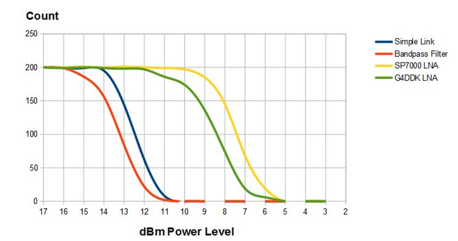
With the figures collected, I used a spreadsheet and graph to visualise the results, see below. On the graph an improvement in performance will shift the trace to the right.

The bandpass filter seems to have little beneficial effect, reception is in fact slightly worse (shifted left in the graph) and seems to match the reduction expected by the insertion loss of the filter.
The SP7000 LNA did have a beneficial effect link performance improved by around 5dBm, but not a much as would be expected with with non LoRa® systems.
The lower cost LNA was also an improvement, at around 4dBm.
From this testing at SF7, then there is a small benefit to using an LNA, but at an increase in complexity and cost. The LNA either needs to be in a receive only path or you need the auto switching of the SP7000 or an additional antenna sequencer.
Next, I will see what happens if you carry out the same tests at SF12, which is operating at 20dB below noise level.
SF12 Tests
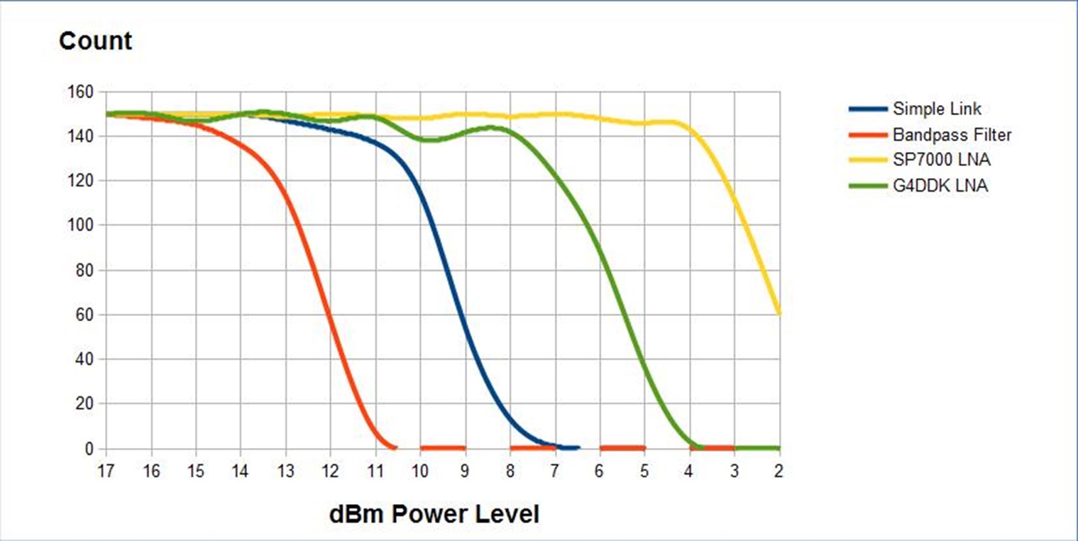
I repeated the same tests at SF12, and the results were a surprise. Since SF12 operates at up to –12.5dB bellow noise over SF7 (the previous tests described above) I had expected the LNAs to have a lesser effect, the reverse proves to be the case. See the graph below;

Here the the SP7000 LNA (yellow trace) added around 7dB signal gain over the Simple link (blue trace) and the G4DDK (green trace) added 3.5dB. More gain at a lower spreading factors is less of an issue since you can perhaps increase the spreading factor to compensate if you want more distance. However at SF12 you are at the limit, so the extra 7dB of link margin from a good LNA would approximately double the distance the SF12 packets would reach. This could have a significant benefit in some applications.
Stuart Robinson
January 2018