Seeeduino XIAO - Part 3
Seeeduino XIAO - Part 3 - StuartsProjects XIAO LoRa Board
A previous article; https://stuartsprojects.github.io/2022/10/03/Seeeduino_XIAO.html I discussed the basics of the XIAO SAMD21 and more detail was added in part 2.
In part 2 code was presented that allowed the XIAO SAMD21 to read a GPS and show the co-ordinate data on an OLED display. To move on to using the XIAO for a GPS tracker we need to add LoRa transmission and receive functions. That is straightforward and there is demo code for LoRa transmit and receive at the repository Board for XIAO LoRa. Whilst you can build the parts of a GPS tracker on a breadboard, its not really much use, to make the GPS tracker small and portable it needs to be on a PCB and battery powered.
Whilst the board was initially designed for the XIAO SAMD21, you can fit the XIAO RP2040 and you will find some programs for the RP2040 version in the boards repository.
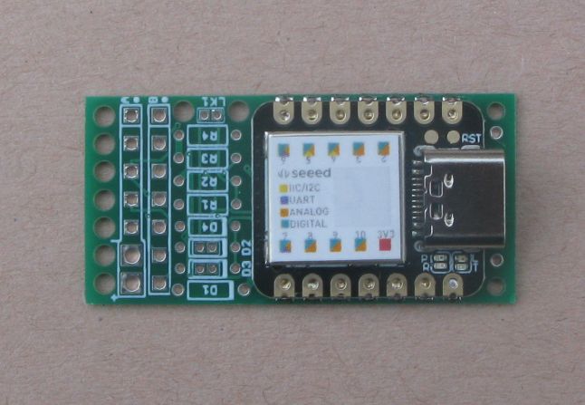
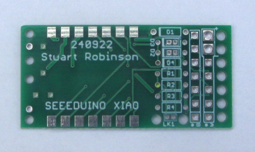
The XIAO and a LoRa RFM9X module can be surface mounted on a PCB, there is no need to use pins and the soldering is not difficult. Whilst it would be possible to lay out a PCB that would allow the XIAO and RFM9X to be soldered in place with pins, the PCB would be much longer and thicker, so lets start at the beginning, we need a PCB, and here it is, the StuartsProjects XIAO LoRa Board with the XIAO mounted;
What is described below is applicable to other applications apart from GPS trackers. The board has both I2C, Serial UART ports, or up to 5 digital or analogue pins suitable for a wide variety of applications.
The RFM9X LoRa device fits on the back and uses a simple wire or you can connect an external antenna if you fit an u.fl socket. The component count has been minimised in order to keep the board small. There are some optional resistors and diodes that are wired types so soldering is easy. If you just want to add a Serial device (such as a GPS) or a Sensor (such as and I2C BME280) then the end of the PCB has two 0.1” connectors to plug them in. You can either use 0.1” pin headers or wire them direct, the large holes at the end of the PCB can be used as strain relief’s or for securing wires with small zip ties.
External connections
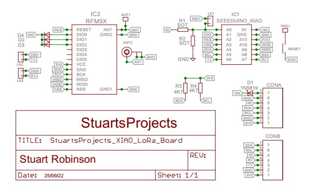
If you look at the connections for the two 7 pin connectors at the end of the board;
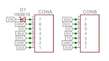
You will see that CONA is for I2C devices and CONB has the serial UART connections for GPS devices etc. Each connector also has a pin labelled IO which is pin A0 of the XIAO. There are two resistors you can connect to the IO pin;
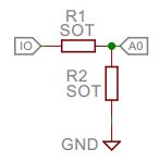
You can use fit these resistors in a number of ways;
- Fit suitable R1 and R2 as a voltage divider to read the voltage on IO using A0 as an analogue pin.
- Fit R1 as a current limit resistor for driving components such as an LED.
- Fit a high value for R1 as a current limit resistor to allow the reading of a higher voltage on IO.
- For a direct digital read at 3.3V logic levels, fit a wire link in place of R1.
SOT is an abbreviation for select on test.
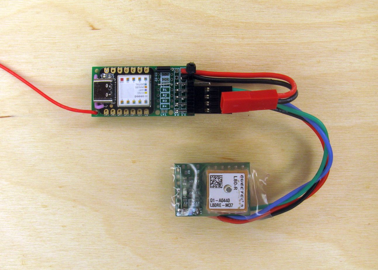
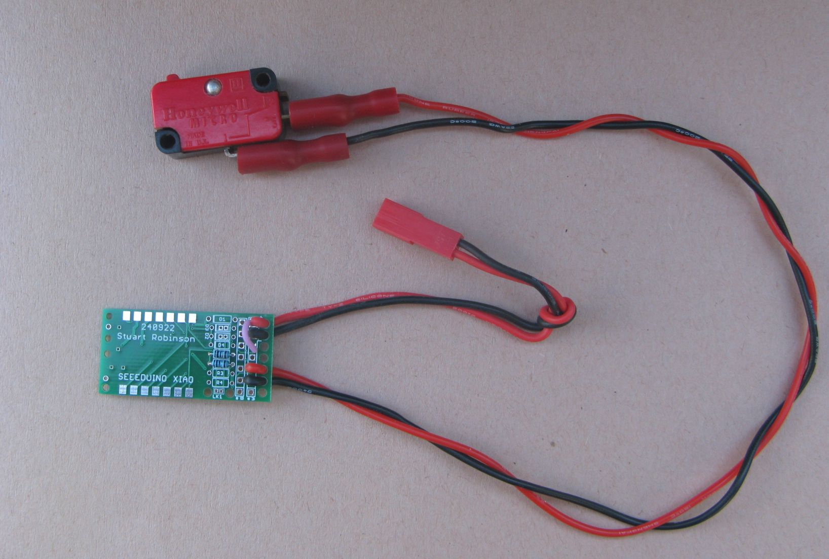
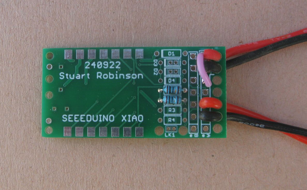
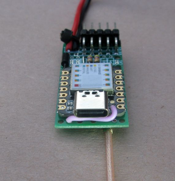
Below is an example of using the holes in the end of the board as strain relief’s, in this case there is a battery lead and note the short purple wire which connects a voltage divider to the battery input so that the volts can be read on the IO pin (A0).
There is also shown a connection to a micro switch which is read on the A5 pin, this switch could be used a door open detector for instance, waking the board up and having it send a LoRa packet.
Board assembly.
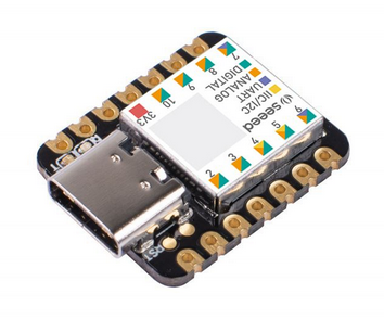
First check that you can load the XIAO with sketch 1_LED_Blink and see the serial output, a seconds count, in the serial monitor.
![]()
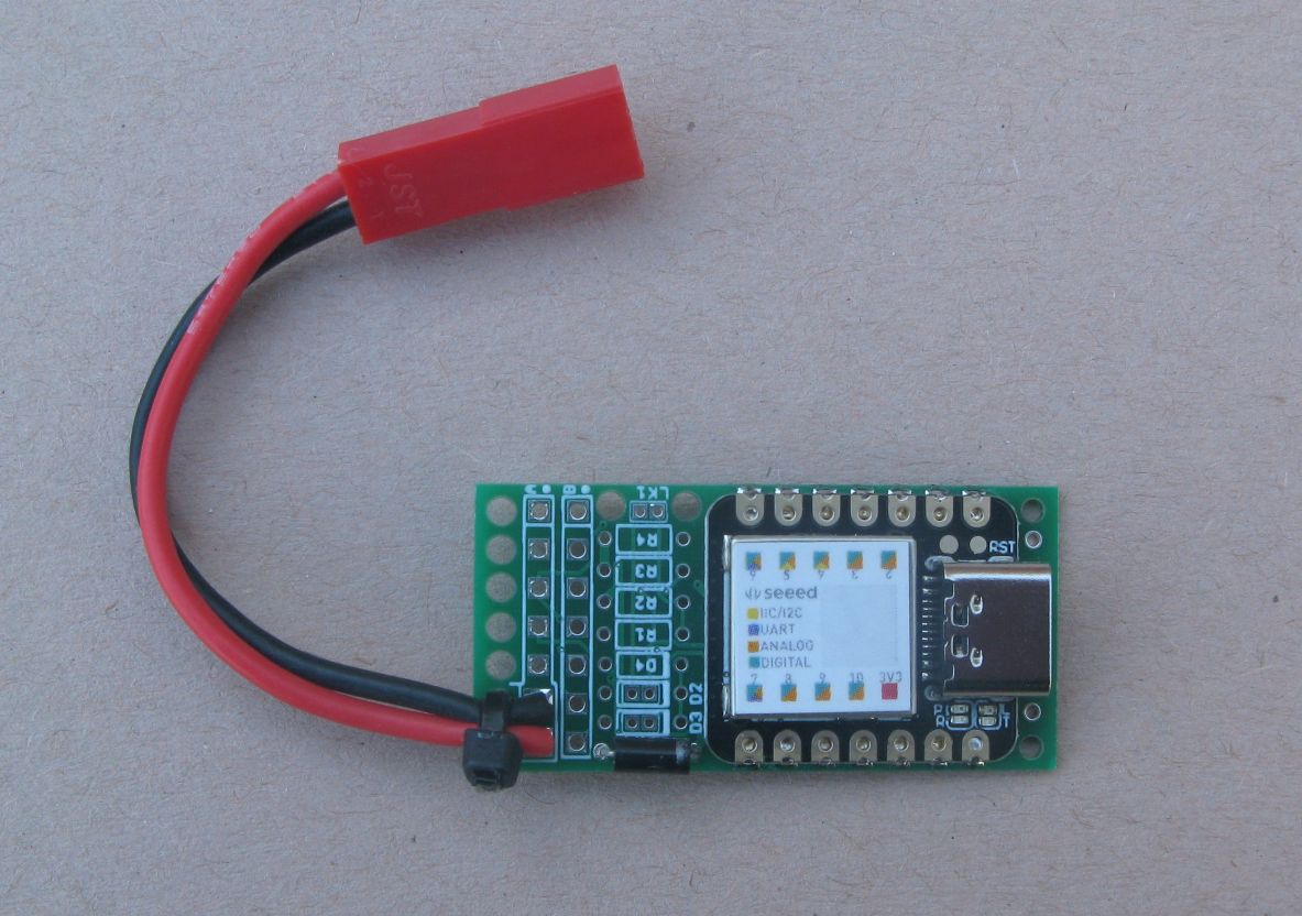
Add the diode D1, IN5819, that’s there to protect against reverse battery connections, fit a wire link here if your not concerned about reversing the battery connection. Connect a battery up using the pins marked + and -, see the picture below. I am using a silicone JST lead. The batteries I used were standard AAA Alkalines, 3 off them will supply enough voltage for the XIAO.
AAA Lithium Energizers, are better for trackers. Their voltage will be stable to 1.5v until almost completely exhausted, so with three you have a 4.5V supply for the majority of the batteries life. Alkalines will be down to 1.2V about halfway through their life, not so good. The AAA Alkalines weigh 11.14g each, the Lithium’s 7.49g.
Next I added a 2 row 5 pin angled header at the end of the PCB, this would allow me to plug in a serial GPS and an I2C sensor or display. The pins could be used for switching or driving other stuff, they don’t have to be used for serial or I2C.
Here is the board showing the with the pin header added to the end.
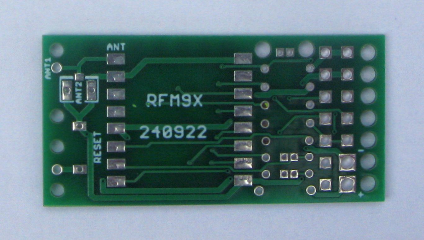
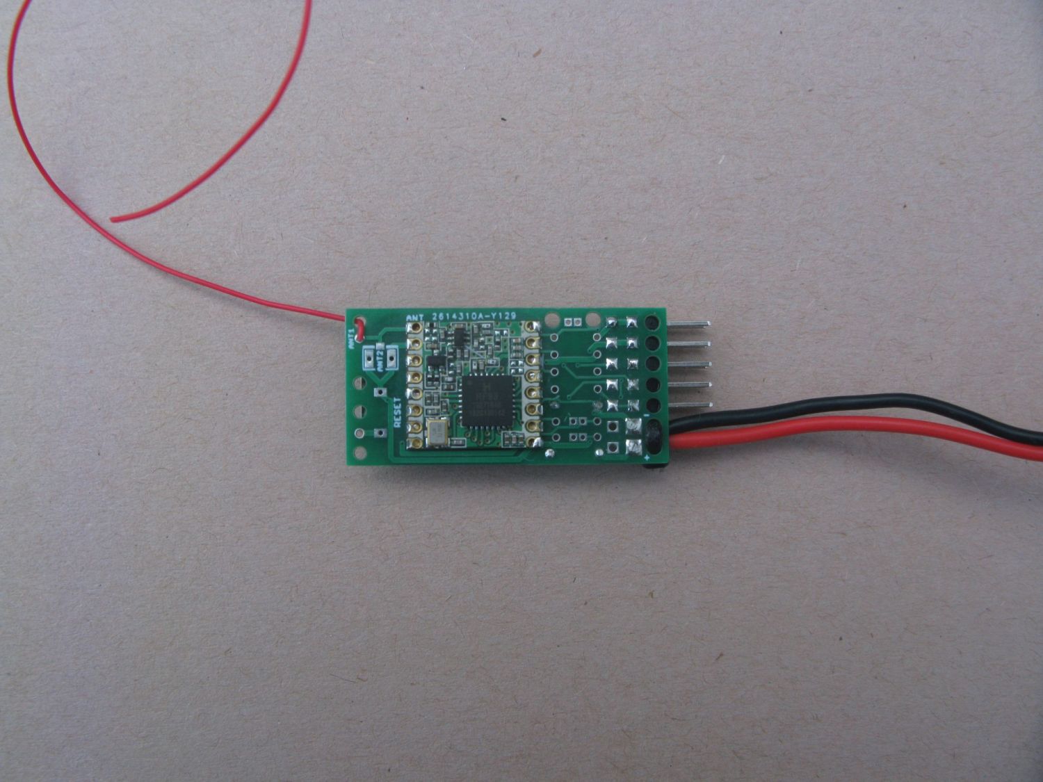
Turn the board over and solder the RFM9X in place, note the connection marked ‘ANT’ on the underside of the RFM9X PCB goes to the solder pad marked ANT on the PCB bottom.
Add a 17cm length of wire as an antenna, this is the correct length for 434Mhz, the wire end is soldered into the round solder pad\hole next to the ANT pin. Loop the antenna wire back through the hole next to the pad so there is a strain relief on the soldered connection.
You need to decide how to connect up the DIO pins on the RFM9X or the LoRa examples will not work. There are several options for connecting up the DIO pins on the RFM9X. You can connect DIO0,DIO1 and DIO3 up to be read on the same XIAO pin A1 by fitting diodes D2, D3, D4. The LoRa library used for examples here only reads DIO0 on the RFM9X, so fit D4 or just a wire link.
If you have an application, such as LoRaWAN, that needs individual access to DIO1 and DIO2 also, do not fit D2 and D3, but fit wire links LK2 and LK3 which are in the D2 and D3 diode positions respectively. You will loose access to the default serial UART port, but DIO1 will be on pin A6 and DIO2 will be on pin A7.
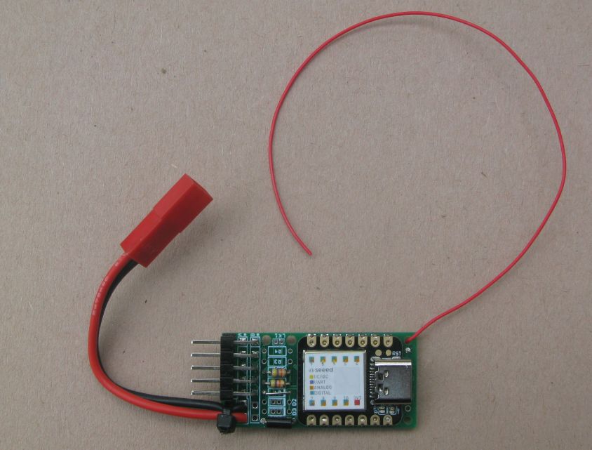
Here is the board with the RFM9X and wire antenna in place;
Load up the program 3_LoRa_Transmitter and if all is well the XIAO pin 13 LED should blink about once a second indicating a transmitted packet. If something is wrong then the LED might flash rapidly or the LED will blink about once every 10 seconds indicating a transmit time-out.
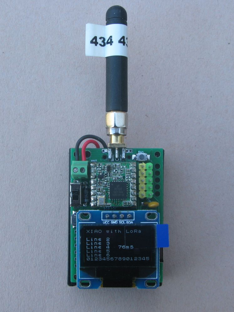
Ideally you would have another Arduino with a LoRa module that is running program 4_LoRa_Receiver which would tell you if the transmitter is sending OK packets. You could load the receiver program into another of these boards, or there is different board, coming soon, which has a display and is designed as a small portable receiver for the tracker.
To use the board as a working tracker, load up program, 15_GPS_Tracker_Transmitter and connect a GPS to the board. If you place it outside with a good view of the sky, it should within 45 seconds or so start transmitting GPS location packets. These packets can be received by another Arduino running program 16_GPS_Tracker_Receiver_With_Display_and_GPS which again could be another StuartsProjects XIAO LoRa board, see below;
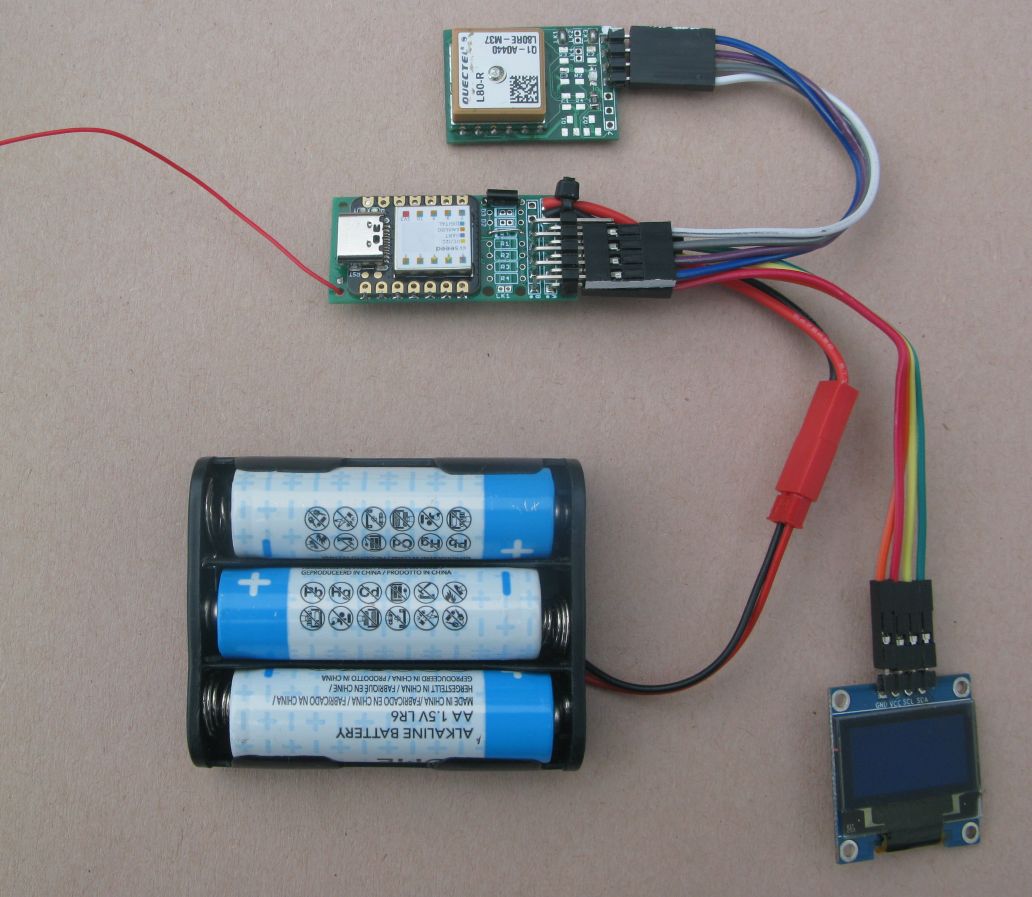
Note that the receiver program, if fitted with a GPS and assuming the receiver’s GPS can get a good signal, will on receipt of a location packet from the tracker transmitter, calculate and show the distance and direction of the tracker from the receiver.
If you want the transmitter to send the battery voltage with the location packet you will need to fit R1 and R2 and the wire link described above. I used 100K resistors for R1 and R2
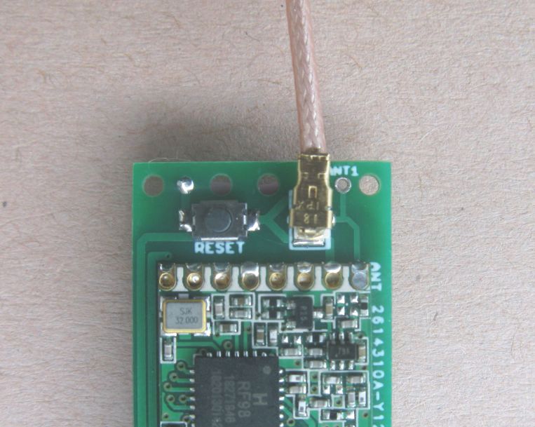
Reset switch and u.fl socket
The u.fl socket is surface mounted on the pads next to the ANT1 hole where the plain wire antenna fits. Don’t use the wire antenna if you have another antenna or cable connected to the u.fl socket. See the left picture below.
On the LoRa side of the board you can fit a small surface mount reset switch, which makes loading programs a bit easier. You need to fit a short wire, its the purple one in the right picture below, to the small gold reset pad on the XIAO and then run this wire in the gap between the USB socket and the board. Then solder the short wire into the solder pad\hole that goes to one of the reset switch pads on the LoRa module side of the board.
![]()
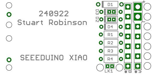
The boards
The board files in Eagle PCB format can be found in this device repository;
The device repository has example programs, build instructions and layout diagrams also.
LoRa settings for range.
LoRa can use a variety of settings which affect the distance or range at which they can be picked up. The example programs discussed here use Spreading factor 7, bandwidth 125000hz and coding rate 4:5. The GPS tracker packet length is 31 bytes and that would have an air time of 70ms. If you change the LoRa settings to Spreading factor 12, bandwidth 62500hz and coding rate 4:5 the air time increases to 3200mS. This is a long (in time) packet and the distance or range it would be received at increases by about a factor of 8.
Also be aware that while packets that take a long time to send sound OK because they go a lot further, be aware of legal duty cycles for your part of the world. In the 434Mhz band you often can only transmit 10% of the time. In these circumstances you could only send one of those long distance 3200mS packets once every 32 seconds.
Coming soon: Very easy build XIAO hand held LoRa transmitter and receiver.