Seeeduino XIAO
Seeeduino XIAO
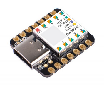
The XIAO SAMD21 is an interesting board, Arduino IDE compatible, plenty of Flash (256KB) and RAM (32KB) and uses an ARM® Cortex®-M0+ (SAMD21G18) running at up to 48MHz.
There was mention of the XIAO in the cycle alarm project described here; https://stuartsprojects.github.io/2022/09/08/Cycle-Alarm-Extender.html
A big plus of the XIAO is that it’s real small, 21mm x 17.5mm, and easy to use in a project, you can connect it to a PCB either with 0.1” pin headers or solder it surface mount style.
The small size means it could be useful for very small GPS trackers or sensor nodes.
And its low cost too.
The repository for the XIAO example programs described in this article are here; Board for XIAO LoRa
Seeeduino XIAO and LoRa
I wanted to check the XIAO runs with LoRa, so I connected an RFM95 up as follows;
LoRa GND - XIAO GND
LoRa 3V3 - XIAO 3V3
LoRa NSS - XIAO A3
LoRa SCK - XIAO A8
LoRa MISO - XIAO A9
LoRa MOSI - XIAO A10
For this first test I left the LoRa device NRESET and DIO0 (and all other pins) floating. Program 2_LoRa_Register_Test is a standalone program that reads the LoRa device registers and prints them to the serial monitor. Its useful as a first level check that the LoRa device is connected. If the register test shown the device can be read, its very likely its going to work as a transmitter and receiver.
Next program to test is 3_LoRa_Transmitter which uses the SX12XX-LoRa library to transmit a LoRa packet on a regular basis. Note you will need to add these connections;
LoRa DIO0 - XIAO A1
LoRa NRESET - XIAO A2
A matching receiver for general Arduino boards will be found in the \examples\Basics folder of the SX12XX-LoRa library.
The repository for the XIAO does have program 4_LoRa_Receiver which is a receiver for the XIAO.
Programs 3_LoRa_Transmitter and 4_LoRa_Receiver show that the XIAO works with the SX12XX-LoRa library.
Note that the frequency settings of 434000000 used in the setup line;
LoRa.setupLoRa(434000000, 0, LORA_SF7, LORA_BW_125, LORA_CR_4_5, LDRO_AUTO);
Must match the LoRa module in use, 434000000 is 434Mhz, so you will need the appropriate LoRa module for this band.
XIAO Sensors
One key consideration for remote sensor nodes is that they have a low sleep current. A sensor might often be used for say monitoring the temperature of a greenhouse so it may only be sending data home once every 10 minutes or so. Most of the time then the sensor will be doing nothing, just waiting for the next transmit time.
During the wait time you don’t want the sensor to use a lot of battery power. The XIAO SAMD21 running a simple code loop (but not transmitting) consumes around 12mA, and if that was the current consumption all the time, a set of AAA Alkalines would only last 3 days or so which is not very practical for a remote sensor.
The way of increasing battery life is to put the micro controller and attached devices into so called sleep mode. For instance if the running current was 10mA and the sleep current was 1000 times less, (10uA), the battery life would be 1000 times what it was at 10mA, which would be 4000 days in this example. Now just over 10 years of battery life makes the sensor far more practical and much cheaper to run.
The LoRa modules themselves do have a very low sleep current, less than 1uA. In this mode all register settings are retained meaning its ready to go when the processor wakes up. Although note its not too much of a problem to re-initialise the LoRa module when the sensor wakes up, an XIAO will setup an RFM95 LoRa device in 40mS, when using my SX12XX-LoRa Library, 40mS at 10mA is not a lot of power.
Modify XIAO for low current sleep
Unfortunately the XIAO has a power LED which is on all the time the XIAO is powered, this consumes 1mA so in effect ruins the low sleep current capability of the XIAO. So for the following tests, which measure the sleep mode current of the XIAO, this LED was removed, see the location of the LED in the picture below, its highlighted in red;
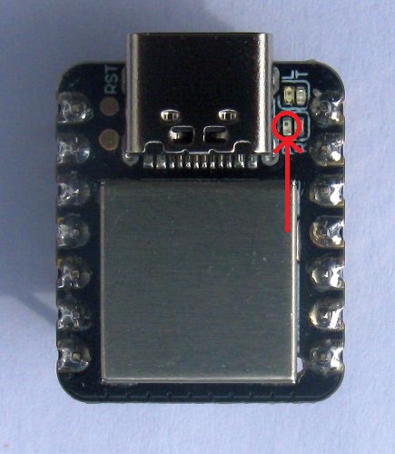
I removed the LED with a fine tipped soldering iron.
Waking up Sensors
So once the XIAO is asleep, how do we wake it up ? There are basically two options;
Wakeup from external interrupt
The processor in the XIAO can be put to sleep such that if there is a logic level change on an GPIO pin, either high going low or low going high, this causes an interrupt which wakes the XIAO from its slumbers. This interrupt could be a switch that operates when a gate opens or a float switch in a tank of liquid activates.
This is the program, 5_WakeUpOnExternalInterrupt which when running connect A6 to GND to wake the XIAO up.
/*******************************************************************************************************
  Programs for Arduino - Copyright of the author Stuart Robinson - 05/10/22

  This program is supplied as is, it is up to the user of the program to decide if the program is
  suitable for the intended purpose and free from errors.
*******************************************************************************************************/

/*******************************************************************************************************
  Program Operation - This program puts an XIAO into deep sleep mode ready to be woken up by an external
  switch.

  Serial monitor baud rate is set at 115200.
*******************************************************************************************************/
#include "ArduinoLowPower.h"   //get library here > https://github.com/arduino-libraries/ArduinoLowPower

#define LED1 13 //on board LED, yellow
#define SWITCH1 A6  //switch pin, used to wake processor up


void loop()
{
  Serial.println(F("Sleeping zzzzz...."));
  Serial.println();
  Serial.flush();
  delay(2000);
  digitalWrite(LED1, HIGH);//make sure LED off when in sleep

  LowPower.deepSleep();

  led_Flash(10, 50);   //10 quick LED flashes to indicate program re-start

  Serial.println(F("Awake !"));
  Serial.flush();
  led_Flash(60, 500);  //60 1 second LED flashes to indicate program awake
}


void wakeUp()
{
  //handler for the interrupt
}


void led_Flash(uint16_t flashes, uint16_t delaymS)
{
  uint16_t index;
  for (index = 1; index <= flashes; index++)
  {
digitalWrite(LED1, LOW);
delay(delaymS);
digitalWrite(LED1, HIGH);
delay(delaymS);
  }
}


void setup()
{
  pinMode(SWITCH1, INPUT);
  pinMode(LED1, OUTPUT);

  led_Flash(2, 125);   //two quick LED flashes to indicate program start

  Serial.begin(115200);
  Serial.println();
  Serial.println(F("5A_WakeUpOnExternalInterrupt Starting"));

  LowPower.attachInterruptWakeup(SWITCH1, wakeUp, CHANGE);  //setup interrupt for wake up
}
And that is it, the board just sits there waiting for A6 to be grounded, in this sleep mode the current consumption is 19uA.
Wakeup after a set time interval
The XIAO processor has an internal real time clock, with an alarm, so its possible to set the time and date when the processor will wake up. You have these options for the alarm;
- MATCH_SS: generate an alarm on seconds match;
- MATCH_MMSS: generate an alarm on minutes and seconds match;
- MATCH_HHMMSS: generate an alarm on hours, minutes and seconds match;
- MATCH_DHHMMSS: generate an alarm on day, hours, minutes and seconds match;
- MATCH_MMDDHHMMSS: generate an alarm on month, day, hours, minutes and seconds match;
- MATCH_YYMMDDHHMMSS: generate an alarm on year, month, day, hours, minutes and seconds match;
Here is the test program 6_RTCAlarm_Sleep_Wakeup ;
/*******************************************************************************************************
  Programs for Arduino - Copyright of the author Stuart Robinson - 05/10/22

  This program is supplied as is, it is up to the user of the program to decide if the program is
  suitable for the intended purpose and free from errors.
*******************************************************************************************************/

/*******************************************************************************************************
  Program Operation - This program is for the Seeeduino XIAO. It flashes the on board LED for one minute,
  then sets the RTC alarm and goes into deep sleep until the alarm occurs.

  Sleep current using this mode of RTC wakeup was 4.7uA.

  Serial monitor baud rate is set at 115200.
*******************************************************************************************************/

#include <RTCZero.h>//get the library here > https://github.com/arduino-libraries/RTCZero
#include "ArduinoLowPower.h"//get library here > https://github.com/arduino-libraries/ArduinoLowPower

RTCZero rtc;//Create an RTCZero object

bool alarm = false;

#define LED1 13


void loop()
{
  led_Flash(60, 500);   //1 second LED flashes for a minute

  rtc.setTime(0, 0, 0);
  rtc.setAlarmTime(0, 0, 15);   //set alarm for 15 seconds
  rtc.attachInterrupt(alarmMatch);
  rtc.enableAlarm(rtc.MATCH_HHMMSS);
  Serial.println(F("Waiting"));
  Serial.flush();
  delay(2000);

  LowPower.deepSleep();

  alarm = false;
  rtc.disableAlarm();
  Serial.println(F("Alarm !"));
  led_Flash(10, 50);
}


void alarmMatch()
{
  alarm = true;
}


void led_Flash(uint16_t flashes, uint16_t delaymS)
{
  uint16_t index;
  for (index = 1; index <= flashes; index++)
  {
digitalWrite(LED1, LOW);
delay(delaymS);
digitalWrite(LED1, HIGH);
delay(delaymS);
  }
}


void setup()
{
  pinMode(LED1, OUTPUT);
  led_Flash(2, 125);   //two quick LED flashes to indicate program start

  Serial.begin(115200);
  Serial.println();
  Serial.println(F("7_RTCAlarm_Sleep_Wakeup Starting"));
  Serial.println();

  rtc.begin(); //initialize RTC 24H format
  rtc.setDate(26, 9, 22);
}
The above program sleeps the XIAO for 15 seconds, wakes up, flashes an LED for 60 seconds and goes back to sleep again. The current used in this sleep mode was 4.7uA. Which is very low, more than low enough for sensors running on batteries that that need to spend most of their time asleep.
Sensor examples
Having sorted out how to sleep and wake up the XIAO, we can see what happens when we add LoRa transmit capability.
Note that the frequency settings of 434000000 that are defined in the following programs Settings.h file;
const uint32_t Frequency = 434000000; //frequency of transmissions in hertz
Must match the LoRa module in use, 434000000 is 434Mhz, so you will need to use the appropriate LoRa module for this band. For other bands, 868Mhz or 915Mhz, use appropriate LoRa modules and frequency settings.
The first example is 7_LoRa_Transmitter_Sleep_Switch_Wakeup and this wakes up when a switch is activated, sends a message “Gate Open” and then goes back to sleep. The receiver could then detect the “Gate Open” message and act appropriately. In this sleep mode the sleep current consumption was 20uA.
The second example is 8_LoRa_Transmitter_Sleep_RTC_Wakeup which is the sort of program you would use to send a regular update from a sensor, such as the temperature sensor in a greenhouse. Every 5 minutes the processor wakes up and sends the message ‘25C”. The packet send is the contents of the buffer (buff) defined here;
bool Send_Test_Packet()
{
  uint8_t bufffersize;
  uint8_t buff[] = "25C";
In this sleep mode the sleep current consumption was 6uA.
The first two characters of the buffer sent could be amended to reflect the actual temperature read.
Coming soon: GPS tracker applications for the XIAO