Seeeduino XIAO - Part 2
Seeeduino XIAO - Part 2
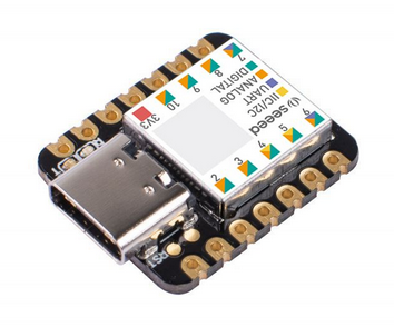
The previous article; https://stuartsprojects.github.io/2022/10/03/Seeeduino_XIAO.html discussed the basics of the XIAO. The XIAO is Arduino IDE compatible, has plenty of Flash (256KB) and RAM (32KB). It uses an ARM® Cortex®-M0+ (SAMD21G18) running at up to 48MHz.
In this article the potential for the XIAO being used as a GPS tracker will be discussed. Initially the example programs described here were tested on a breadboard setup for the XIAO, but an upcoming article will describe a small circuit board that makes the construction of small GPS tracker transmitters and receivers very easy. Testing the programs on a breadboard first makes a lot of sense, you know you have good working examples to use to test a new PCB layout.
Of course what is described here is applicable to other applications apart from GPS trackers. The board mentioned above has both I2C, Serial UART ports, or up to 5 digital or analogue pins for a wide variety of applications.
Connecting the GPS to a serial port
We first need to check that the XIAO can read the characters coming from the GPS correctly. This is straight forward using a simple GPS Echo test.
The program is 9_GPS_Echo_Serial1. The first Serial port is the one normally used to print messages to the Arduino IDE serial monitor, this has the reference Serial. A second serial port is connected to the XIAO pins A6 (TX) and A7 (RX), this serial port has the reference Serial1. Connect the GPS RX pin to XIAO A6 (TX) and GPS TX pin to XIAO A7 (TX).
A program to copy the Serial output of the GPS to the Arduino serial monitor is fairly simple (program 9_GPS_Echo_Serial1);
void loop()
{
  while (Serial1.available())
  {
    Serial.write(Serial1.read());
  }
}


void setup()
{
  Serial1.begin(9600);
  Serial.begin(115200);
  Serial.println("9_GPS_Echo_Serial1 Starting");
}
This is typical output the program produces from a GPS just after switch on;
$GPGLL,,,,,000005.100,V,N*7E
$GPRMC,000006.100,V,,,,,0.00,0.00,060180,,,N,V*3F
$GPVTG,0.00,T,,M,0.00,N,0.00,K,N*32
$GPGGA,000006.100,,,,,0,0,,,M,,M,,*4F
$GPGSA,A,1,,,,,,,,,,,,,,,,1*03
$GPGSA,A,1,,,,,,,,,,,,,,,,2*00
$GPGSV,1,1,00,0*65
$GLGSV,1,1,00,1*78
And after a few seconds, if the GPS is outside with a good view of the sky it should pick up the time (14:35:03) in this case;
$GPGLL,,,,,143502.089,V,N*7A
$GPRMC,143503.089,V,,,,,0.00,0.00,140922,,,N,V*3A
$GPVTG,0.00,T,,M,0.00,N,0.00,K,N*32
$GPGGA,143503.089,,,,,0,0,,,M,,M,,*49
$GPGSA,A,1,,,,,,,,,,,,,,,,1*03
$GPGSA,A,1,,,,,,,,,,,,,,,,2*00
$GPGSV,1,1,01,30,,,33,0*67
$GLGSV,1,1,00,1*78
Using the GPS on another serial port
It might not always be possible to have pins A6 and A7 on the XIAO free to connect the GPS, but its possible to redirect the serial ports via a Sercom configuration. In the example below we will connect the GPS to the port normally used for I2C connections, XIAO pins A4 and A5. Connect the GPS TX pin to XIAO A5 (RX).
The program is 10_GPS_Echo_Sercom2
#include <Arduino.h>
#include "wiring_private.h" //for pinPeripheral() function

Uart Serial3(&sercom2, A5, A4, SERCOM_RX_PAD_1, UART_TX_PAD_0);

volatile int serviceCount3 = 0;

extern "C"
{
  void SERCOM2_Handler(void)
  {
   serviceCount3++;  //to check this handler is used
   Serial3.IrqHandler();
  }
}


void loop()
{
  if (Serial3.available())
  {
   Serial.write(Serial3.read());
  }
}

void setup()
{
 Serial.begin(115200);
 Serial.println("10_GPS_Echo_Sercom2 Starting");
 delay(2000);
 pinPeripheral(A3, PIO_SERCOM_ALT);
 pinPeripheral(A2, PIO_SERCOM_ALT);
 Serial3.begin(9600);
}
Adding a display
For a basic GPS application we can use a small OLED display to show the location the GPS is reporting. The are 0.96” and 1.3” OLED displays which are 128 x 64 pixels, so enough for a small amount of text. These displays are connected via I2C so we only need to use 2 GPIO pins on the XIAO.
A useful program to have at this point is an I2C scanner. Its a program that checks the I2C bus for devices and reports back if a device is found. A typical I2C small OLED is normally on address 0x3C and this is the address a library for the OLED will expect the display to be at. If the display is not on this address then the library needs to know the correct address. This is the program (11_I2C_Scanner);
#include <Wire.h>


void loop()
{
  uint8_t I2Cstatus, I2Caddress;
  int16_t I2Cdevicesfound;

  Serial.println("Checking");

  I2Cdevicesfound = 0;

  for (I2Caddress = 1; I2Caddress < 127; I2Caddress++ )
  {
Wire.beginTransmission(I2Caddress);
I2Cstatus = Wire.endTransmission();

if (I2Cstatus == 0)
{
  Serial.print("I2C device at address 0x");
  if (I2Caddress < 16)
  {
Serial.print("0");
  }
  Serial.println(I2Caddress, HEX);
  I2Cdevicesfound++;
}
else if (I2Cstatus == 4)
{
  Serial.print("ERROR at I2Caddress 0x");
  if (I2Caddress < 16)
  {
Serial.print("0");
  }
  Serial.println(I2Caddress, HEX);
}
  }

  Serial.print("I2C devices found ");
  Serial.println(I2Cdevicesfound);
  Serial.println();
  delay(5000);
}


void setup()
{
  Wire.begin();
  Serial.begin(115200);
  Serial.println("11_I2C_Scanner starting");
  Serial.println();
}
And is if by magic, if an OLED is connected to the standard I2C port on the XIAO (A4 = SDA, A5 = SCL) then the program reports;
Checking
I2C device at address 0x3C
I2C devices found 1
Next we need a test program for the I2C OLED, which is 12_SSD1306_SH1106_OLED_Checker. The small OLEDS are of two different types, the smaller 0.96” one is the SSD1306 and the larger 1.3” one is the SH1106. The display library needs to know to display correctly. Typically if the wrong one is selected the extreme left and right of the screen can display odd stuff.
This is the program;
#include <U8x8lib.h>//get library here >  https://github.com/olikraus/u8g2

//Important - select the type of OLED here
U8X8_SSD1306_128X64_NONAME_HW_I2C disp(U8X8_PIN_NONE);  //use this line for standard 0.96" SSD1306
//U8X8_SH1106_128X64_NONAME_HW_I2C disp(U8X8_PIN_NONE); //use this line for the SH1106 1.3" OLED often sold as 1.3" SSD1306

#define DEFAULTFONT u8x8_font_chroma48medium8_r //font for U8X8 Library

uint16_t writecount;
uint32_t startwritemS, endwritemS, timemS;


void loop()
{
  writecount++;
  Serial.print(writecount);
  Serial.print(F(" Writing to display"));

  startwritemS = millis();
  disp.clear();
  screen1();
  endwritemS = millis();
  timemS = endwritemS - startwritemS;
  disp.setCursor(8, 4);
  disp.print(timemS);
  disp.print(F("mS"));

  Serial.print(F(" - done "));
  Serial.print(timemS);
  Serial.println(F("mS"));

  delay(2000);
}


void screen1()
{
  disp.setCursor(0, 0);
  disp.print(F("Hello World !"));
  disp.setCursor(0, 1);
  disp.print(F("Line 1"));
  disp.setCursor(0, 2);
  disp.print(F("Line 2"));
  disp.setCursor(0, 3);
  disp.print(F("Line 3"));
  disp.setCursor(0, 4);
  disp.print(F("Line 4"));
  disp.setCursor(0, 5);
  disp.print(F("Line 5"));
  disp.setCursor(0, 6);
  disp.print(F("Line 6"));
  disp.setCursor(0, 7);
  disp.print(F("0123456789012345")); //display is 8 lines x 16 charaters when using the
}


void setup()
{
  Serial.begin(115200);
  Serial.println(F("12_SSD1306_SH1106_OLED_Checker starting"));
  disp.begin();
  disp.setFont(DEFAULTFONT);
}
Putting it all together
So we have checked the GPS is working, we can scan the I2C bus to check the display address and we have tested the display is working. All we need to do now is have a program that reads the characters coming from the GPS, feeds them into a GPS library and when there is an updated GPS location fix display the data on the OLED display, simple. I wont post all the code on here, but you will find it in program 13_GPS_Checker_With_Display
At this point a warning is needed. If the GPS is located indoors it may not work very well in that it will not provide a location fix, ever. It might maybe work indoors but it could take ages and ages and ages to get a location fix. There is no magic voodoo code to solve this problem, if you want the GPS to work well, take it outdoors, or just wait a while, or maybe wait forever.
So with the GPS in a good location, outdoors with a good view of the sky, if its working properly the display should show a location fix within about 45 seconds of the GPS being powered up.
Measuring battery voltage.
Its very helpful if a GPS tracker can know when the battery is getting low, it can increase the time between transmissions for instance.
Often when using a a resistor divider to measure battery voltage, you don’t want to have it permanently connected. If you used 2 x 10K resistors, they would consume, from a 4.5v battery, 225uA, so wow !. Remember in RTC sleep mode the deep sleep current of the XIAO is only 5uA.
In a lot of circuits I would use this arrangement;
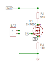
The voltage being read at IO pin A0 is close to 1/10th of the voltage at RAW, which is the battery. With the gate of the MOSFET held low (via GPIO pin 8) the resistor divider is off and it does not use battery current. To read the battery voltage the MOSFET gate must be set high.
Unfortunately The XIAO does not have many available pins and whilst you have to find one to read the battery voltage its hard to find another one to switch in the MOSFET.
So the question is, how high in value can the resistors go and still produce an accurate enough reading ? Remember the higher the resistance the less battery current the resistor divider uses.
I used equal value resistors across VCC (3.3V) and noted the reading;
- 2 x 10K = 2052
- 2 x 47K = 2055
- 2 x 220K = 2044
- 2 x 2.2M = 1948
So you can see the voltage read does drop when the resistor dividers have high values, but that could be accounted for in calibration. The 2 x 2.2M resistors would draw typically 1uA from a 4.5V battery, so there would be no significant impact of battery life.
Once I had worked out a suitable multiplier, 1.628 in this case to convert the average into 3300mV, I let it run for a few minutes and the lowest value I saw was 3263mV and the highest was 3312mV. Given that the resistor divider only consumes 1uA, that level of variation is worthwhile tolerating, and is good enough for detecting a flat battery.
The program used for testing the battery voltage was 14_Battery_Voltage_Read
The repository for the XIAO example programs described in this article are here; Board\_for\_XIAO_LoRa.