Large Data Transfers with LoRa - Part1
I have recently been carrying out some tests with the ESP32CAM connected to a LoRa device, see here;
https://stuartsprojects.github.io/2020/12/17/Easy-ESP32CAM-LoRa-Tracker-Add-On-Board.html
The ESP32CAM as a GPS tracker is shown below;
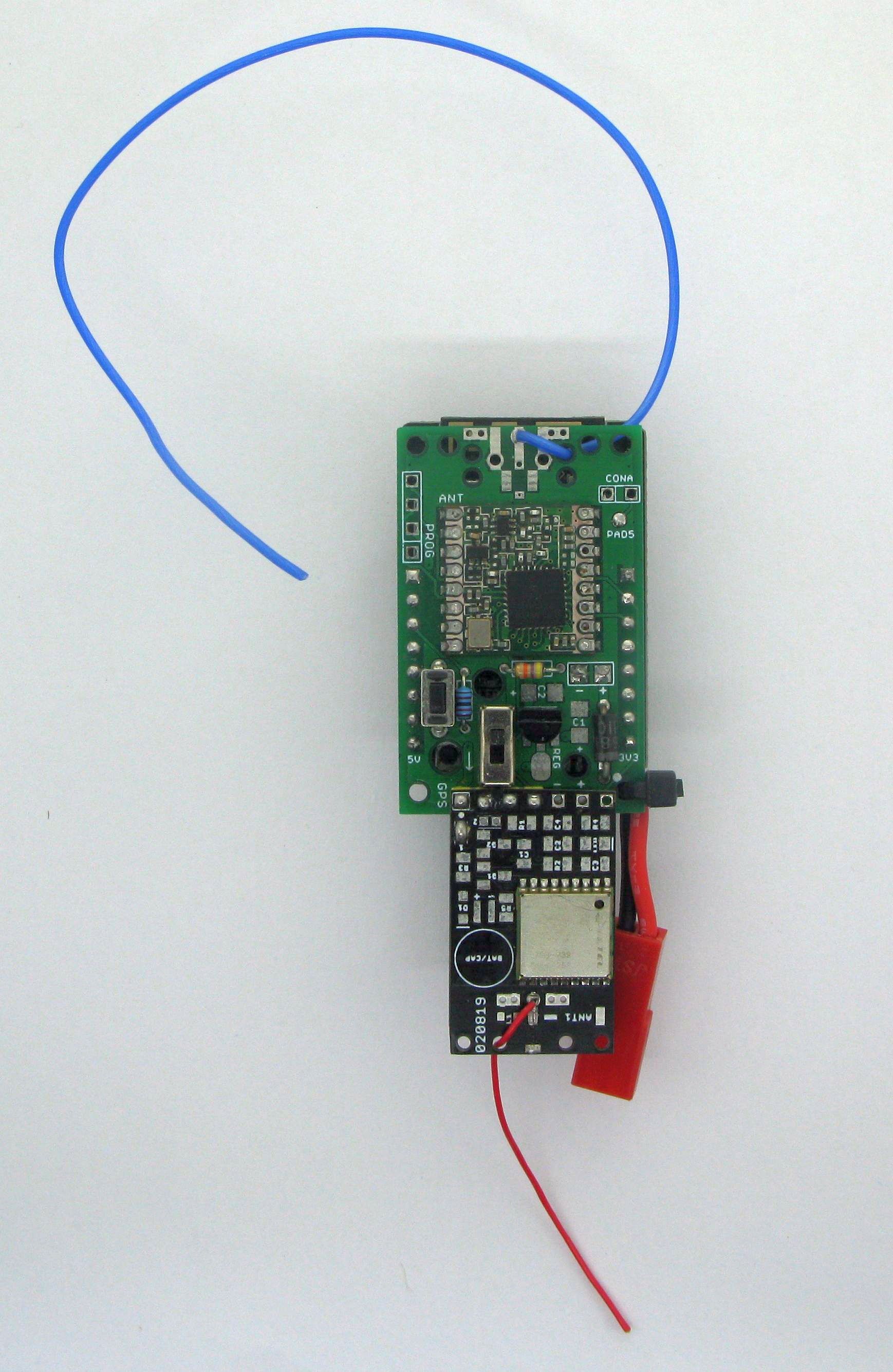
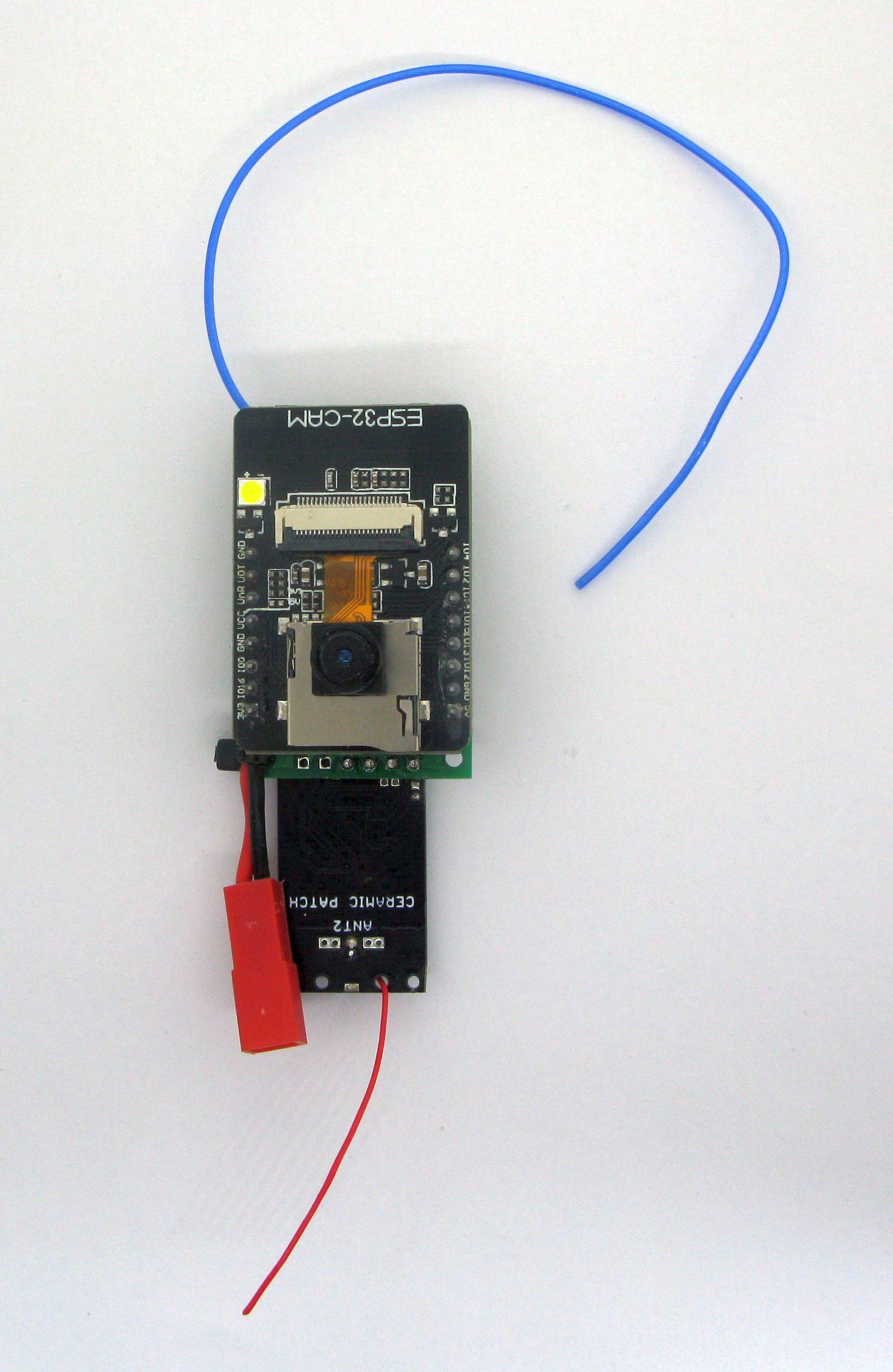
The ESP32CAM is a very low cost camera device and adding a LoRa capability could make long distance monitoring via transferred images possible. The ESP32CAM can independently save images to its micro SD card but what are the project possibilities if those images could be sent over many kilometres via LoRa from one simple Arduino to another ?
I was not just interested in image transfers from high altitude balloon (HAB) trackers but also in applications where the ESP32CAM (or other Arduino) could send images for security or other remote monitoring applications. The ESP32CAM does initially create the image in memory so it ought to be possible to do without its SD card which would then make low sleep current applications possible.
An image might be 64Kbyte to 128Kbyte in size and moving that large amount of data between Arduinos, in a simple and reliable way over long distances, would I thought be an interesting challenge.
Slow Scan Digital Video (SSDV) images have been transferred via LoRa from high altitude balloons and this format does allow for a viewable image to be built even with missing sections. I however, was more interested in a general purpose data transfer Arduino to Arduino application that would be applicable for transferring any file or block of data from the SD card or memory of one Arduino to another using LoRa. I did not want the transfer program limited to a particular format of file.
These data transfers could be over very long distances in the 100km+ region at slow speed using UHF LoRa (434/868/915Mhz) or over short distances say 5km or so at relatively higher speeds using 2.4Ghz LoRa.
If general purpose data or file transfer is to be carried out, pictures or other, then there needs to be a robust and reliable method of transmitting and receiving a long stream of LoRa packets. A single missing byte or bit can corrupt the transfer.
Limitations
The primary limitation of large data transfers in the Industrial Scientific and Medical (ISM) licence exempt bands is the restrictions on duty cycle. Duty cycle restricts the amount of time a transmitter can be active transmitting and it can typically be 1% or 10% at UHF. These duty cycle limits do significantly restrict how much data you can send. At 1% duty cycle your transmitter can be sending data for only 36 seconds in every hour.
One workaround in the UK for UHF is to operate in the 434Mhz band at less than 25Khz bandwidth when the duty cycle can then be 100%, i.e. you can transmit continuously. The highest LoRa data rate at that nearest bandwidth (20.8Khz)is around 2.5Kbs using an SX126x at spreading factor 5. This is a data rate 70% higher than an SX127x can manage. The SX126x also has the advantage of being able to operate reliably at this low bandwidth without the need for the frequency matching and automatic frequency control required for a typical SX127X.
For shorter distances the 2.4Ghz SX1280 LoRa device is a better choice and you can operate at 2.4Ghz at 100% duty cycle. For LoRa settings that should be good for around 5km line of sight with only simple antennas a data rate of up to 200kbps can be used. This high data rate would allow the transfer of a 64Kbyte image in under 10 seconds.
Reliability
It often seems to be assumed that if you send a packet of data over LoRa, or any other radio system, then as long as you are using the devices internal CRC checking then you can assume that on receipt by the receiver the data is ‘valid’ and OK to use.
But can you really be sure the received block\segment of data is valid ?
The receiver could be picking up packets from another transmitter and given the very long range nature of LoRa this other transmitter could be many kilometres away so you may have no idea it’s there. In a dense urban or industrial area what are the chances that there are other LoRa transmitters within range sending out packets that you would rather not receive and could corrupt your transfer ?
The internal CRC checking used by LoRa devices for transmission and reception will not help you to eliminate a received packet that has arrived from such a ‘rogue’ source so you could be allowing corrupted data into an application.
It would be helpful if you could be really (really++) sure that a received packet was actually destined for the particular receiver and that it also contained valid data related to the application the receiver is running. This issue is what got me thinking about how to make packet transmission and reception ‘reliable’.
Ideally the process of sending and receiving a ‘reliable’ packet, would be built into library functions with the transmitter program able to send an array/buffer of data and the receiver to have a way of knowing with a very high level of certainty that the received array/buffer of data was valid.
I had previously written some Arduino sketches that on transmit created a Cyclic Redundancy Check (CRC) on the whole packet and then appended this 16 bit CRC as two bytes to the end of the outgoing packet. On receipt the receiver program would read in the received data array, calculate the CRC of the data locally and compare this calculated CRC with the CRC appended to the end of the packet at transmission time. If these CRCs did not match then this could be assumed to be a rogue packet and ignored. The chance of a rogue packet being accepted as valid would then be around 1 in 65,535 packets.
A 1 in 65,535 risk of accepting a rogue packet is fairly reasonable but with a small increase in overall packet size we can reduce the risk even further.
Packet headers
For application purposes it is useful to have a configurable packet header where you can put control information such as packet sequence number, actions for the receiver to carry out or a means of addressing and controlling a network of many receivers.
If at the transmitter the packet header included a ‘networkID’ number and the receiver was configured with the same ‘networkID’ the receiver can check if the received packet was addressed to that particular receiver. For a 16 bit ID, the chances of that sequence of bytes/bits appearing in the same location in the header from a rogue packet are slim.
The packet receiver can then use the header information such as the the data array CRC together with this unique ‘networkID’ to have in effect a 32bit check on the packet validity.
Sequencing a data transfer
If you are sending a long stream of LoRa packets that are a file, such as a jpg image, then you need to be sure the receiver has had the whole sequence of packets. Remember there could be a thousand or more packets that need to be assembled into a image\file. For an initial implementation a simple approach was to add a segment number to the header, then the receiver will know if its received segments are in the correct order for writing to SD.
With such a programmable header the receiver does need to know where the header ends so that it then knows where the actual data payload starts. To test a working system a few assumptions were needed and for the purposes of this set of routines, I made assumptions that the first 8 bytes of a packet which are the header part will always be;
Byte 0 - PacketType - for instance data segment, file open request or acknowledge
Byte 1 - Flags byte - general purpose pass status bits/flage between TX and RX
Byte 2 - Header length - number of bytes which constitute the header
Byte 3 - Data array length - number of bytes which are the data payload
Byte 4 - NetworkID low byte
Byte 5 - NetworkID high byte
Byte 6 - Data array CRC low byte
Byte 7 - Data array CRC high byte
Following byte 7 other control information can be added such as sequence or segment number but the length of the header in bytes does need to be defined in byte 2. So you do have to plan your header sizes.
I next needed to check the basics of the variable length header and the CRC checking of the data array payload would actually work and the impact of the extra processing on packet throughput. Some simple transmit and receive examples were written that used the header structure above with the addition of a sequence or packet number after the data buffer CRC.
I added routines to a local copy of my SX127X library, generated a test data payload and carried out some throughput tests, initially I wanted to know the impact time wise of carrying out the CRC check on the data payload. The transmit routine would need to generate the initial CRC add it to the header and the receiver would also need to run the CRC on the received data payload. These were the results, on an ESP32 running at the default speed of 240Mhz versus an 8Mhz Arduino Pro Mini for a 128byte payload;
| Processor | TX Routine CRC check | RX Routine CRC check |
|---|---|---|
| ESP32 240Mhz | 40uS | 42uS |
| Arduino DUE 88Mhz | 271uS | 250uS |
| ATMega328 8Mhz | 2848uS | 1792uS |
Based on a set of 434Mhz LoRa modem parameters of spreading factor 7, Bandwidth 500kHz, Coding rate 4:8, that I know would be good for 50km+ line of sight, the air time of a 128 byte payload + 10 byte header would be 86.6mS. So even when using 8Mhz Pro Minis the overhead of the data CRC check was only 2.8mS. When considering a send and acknowledge system, and using ESP32s, the total overhead per 128 byte data segment is only 82us out of a total packet air time of 86,600uS, so the additional time for the CRC checking is of little consequence.
Ultimately it was my intention to use an Arduino DUE as the receiver and that would only have a CRC check overhead of 250uS out of an air time time of 86,600uS.
I had initially thought of using a flag in the header to turn off CRC checking but with such a low overhead I decided not to implement that at this initial stage.
Acknowledgements
At some point the transmitter and receiver will need a form of acknowledgement that messages and data have been been interchanged. Thus the receiver needs to send back some form of acknowledgement to the receiver. The transmitter then needs to know that the acknowledgement it receives has actually come from the intended receiver. An easy way to do that is turn around the transmitted (and received) header as an acknowledgement. This acknowledgement is fairly unique in that it contains a networkID, data array CRC and segment number. The transmitter knows the header sent so can easily check that its copy of the header matches the received acknowledgement.
Code was added to the library such that a call to a transmit routine would repeatedly send a data segment until an acknowledgement was correctly received. There was a programmable limit to the number of re-transmit attempts made.
Using an ESP32 as the transmitter with 434Mhz LoRa modem parameters of spreading factor 7, bandwidth 500kHz, coding rate 4:8, sending 128 byte data segments continuously with no acknowledge, each segment took 88mS to send. When the software was modified for the transmitter to wait for a receiver acknowledge, each segment took 105mS to send and then receive the error checked acknowledge. The overhead of adding an acknowledge is therefore around 20% when working well.
In Part 2 the port of the example programs to the SX128x part of the library will be described so the high data rates and that 2.4Ghz LoRa is capable of can be tested.
Stuart Robinson
February 2021