Easy ESP32CAM LoRa Tracker Add On Board
On a previous revision of this board, since the GPS shares the same serial port that is used for program upload, the GPS could not be connected at the same time as program upload. If the tracker was to be fitted with a lightweight GPS breakout boards for say the Quectel L70\L76 or a UBLOX MAX 8MQ then the GPS would need to be permanently attached but then there would need to be a switch or link on the board to disconnect the GPS TX pin during programming.
I revised the board and at the same time made it easier to build by removing the necessity to fit surface mount (SMD) devices. Even the RFM98 LoRa device can be fitted in place with 2mm spacing pin headers if you don’t fancy soldering SMD.
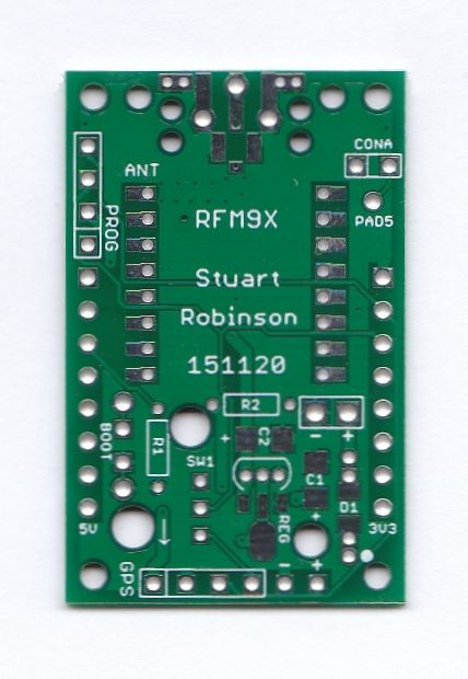
I first built up the board with sockets to plug the board onto the ESP32CAM pin headers to test everything was working OK. The add and board could be removed from the ESP32CAM and the RFM98 was on sockets (2mm spacing) too. I fitted pin headers for the programming and debug connection, although in the built up tracker these would not be needed, test clips can be used instead, which saves weight.
![]()
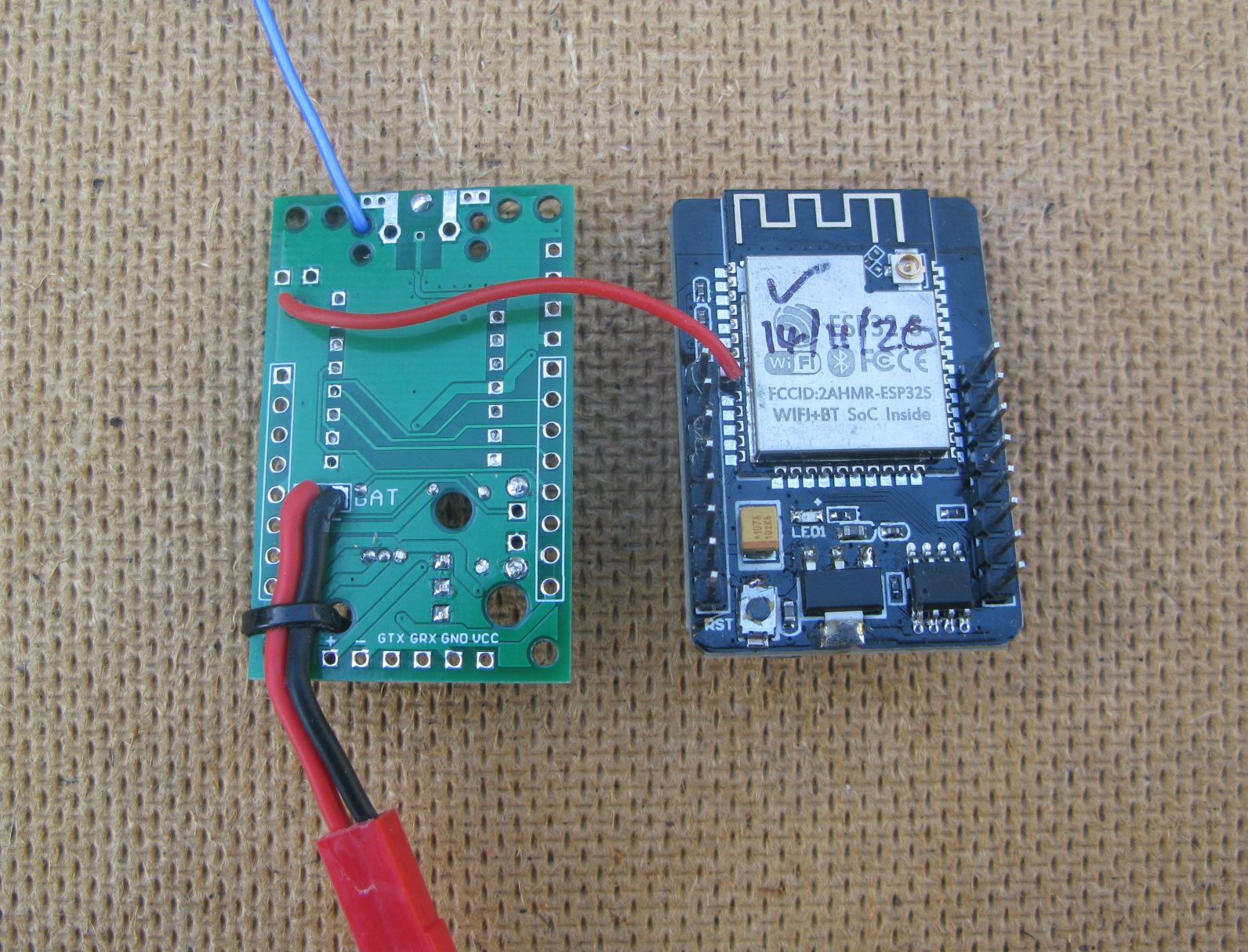
The test build appeared to be working, including the LoRa device, so I assembled another add on board ready for attaching to the ESP32CAM. If you want to use the debug feature you need to attach the wire link (red) from ESP32 pin33 to the pad on the AddOn as shown in the picture.
The regulator fitted on the ESP32CAM is an AMS1117, which is not ideal for a low weight tracker as it needs around 4.6V of input to regulate properly. That would require 4 x AAA batteries or two lithium batteries in series to power it. Not ideal or light. The Tracker AddOn was arranged so that the ESP32CAMs AMS1117 could be removed and an MCP1700 or HCT7833 regulator fitted on the Tracker AddOn would replace it, choice of SOT89 or T092 pin devices. These are true low drop-out voltage regulators and operation from a single lithium battery would now be possible.
The AMS1117 was removed and a TO92 HCT7833 regulator was fitted on the add on board, this is optional, leave the AMS1117 in place if you have high enough voltage batteries.
To the assembled board was added a L70 GPS breakout board and the programming and debug port connections made using test hooks. You can fit pin headers if you want, but it does add a little weight.
![]()
The assembled GPS LoRa tracker ready to go weighs circa 13g, plus the weight of the battery chosen.
![]()
Holes are positioned in the Tracker AddOn board so that when it was soldered in place you could use a rod or drill to access the ESP32CAM reset switch. Another hole allowed you to see the pin 33 LED so it could be used as an indicator. A pad was added so that you could solder a wire to pin 33 of the ESP32 and connect it to the pad on the Tracker AddOn. This then allowed for an external connector for pin 33 so that it could then be used as a serial debug port.
The Easy ESP32CAM tracker board repository can be found here;
And the Quectel L70-L76 GPS board repository can be found here;
The UBLOX MAX 8MQ GPS board repository can be found here;
There was two other posts on the same topic;
ESP32CAM as a High Altitude Balloon Tracker - Really?
Tracker Software
Getting the SD card, where the pictures are stored, working in combination with the LoRa device was tricky due to the shortage of available pins, but the tracker software so-far does manage it. The ESP32 wakes up once a minute, reads the position from the GPS, reads the battery voltage, takes a picture, saves it to SD, sends the LoRa and FSK RTTY and finally goes back to sleep. Once the picture has been saved to SD, it should still be in the ESP32 memory buffer, so it should be possible to send the picture by direct LoRa link. That file transfer software is being worked on.