ESP32CAM as a High Altitude Balloon Tracker - Really?
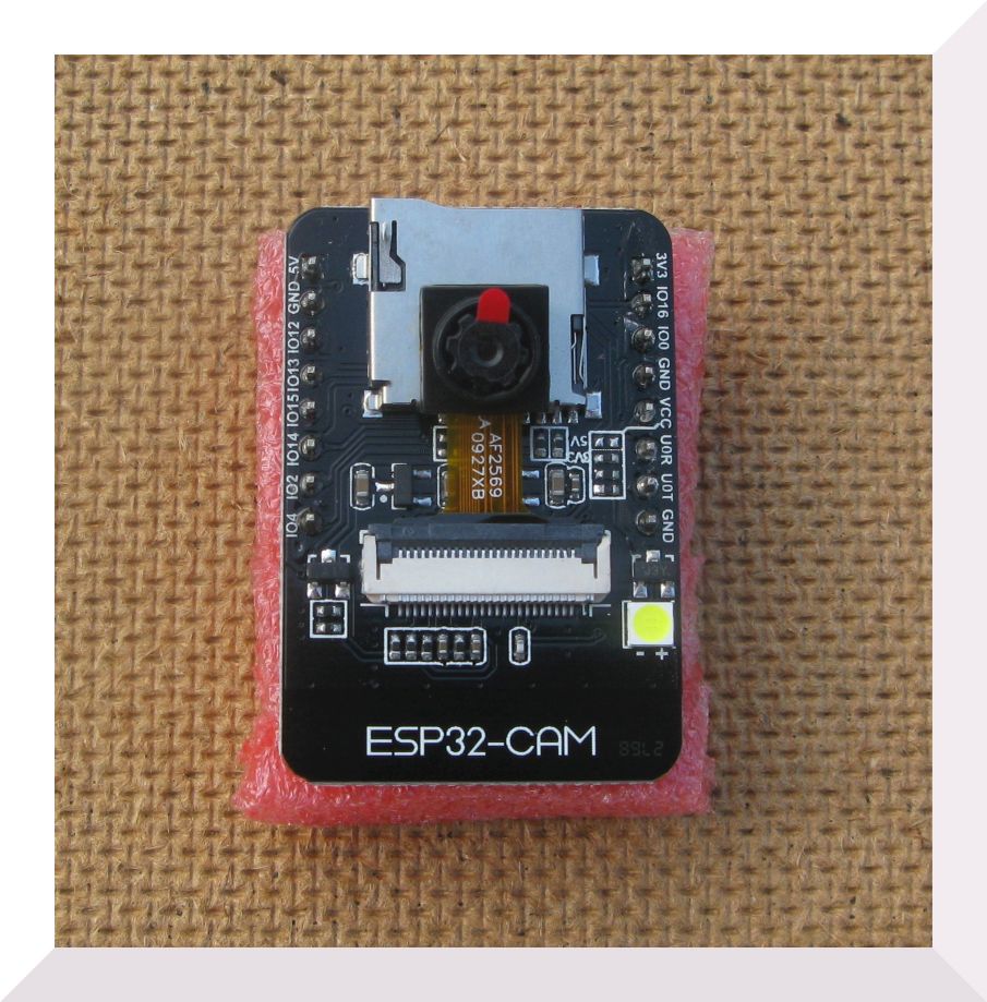
The ESP32CAM is a small and low cost board that contains a ESP32, an OV2640 2.0 mega pixels camera and a microSD card socket. There is a good tutorial by Rui Santos describing the use of the ESP32CAM here. it shows how to take a picture and store it on the microSD card as a JPG.
Accepted that the OV2640 pictures are not brilliant, but then the board is quite small and cheap, but maybe I already mentioned that.
If you could attach a LoRa® device you would have a real cheap board that could potentially transmit pictures over long distances, add a GPS and you could have a high altitude balloon tracker that takes pictures. Unfortunately the IO pins provided on the ESP32CAM are also used for the SD card, so getting a LoRa® device and GPS working is not so straight forward.
First I breadboarded the ESP32CAM and to make life easy for debugging I added a wire to the reset switch so I could connect that externally, the boot pin (that needs to be held low for programming) was already available on the pin headers. I checked that my ESP32CAM was working and could take a picture and store it on SD.
It took a while to find a combination for the pins the SX1278 LoRa® module needed, SCK, MOSI, MISO, NSS, DIO0 and NRESET but eventually I found a combination that did not interfere with the SD card or cause boot problems with the ESP32. I could not find an effective way of driving the NRESET pin which was not too much of a problem, I have left it disconnected on other set-ups and the LoRa® device seems happy to be reliable without needing to be reset at power up or otherwise.
I took the basic ESP32CAM program and added the set-up of an SX1278 LoRa® device from my SX12XX library. If this could be made to work I would at least be able to be notified (via LoRa®) that a remote ESP32CAM had taken a picture. This could be useful for remote monitoring applications or remote downloads for instance.
The basic plan for a working program flow was;
- Wake from sleep
- Print information on boot-count etc.
- Initialise the SPI interface
- Initialise the LoRa® device
- Build a HAB style payload\packet
- Transmit the packet with LoRa®
- Initialise the Camera
- Initialise the SD card
- Take a picture, stored on SD card
- Put board to sleep for X seconds
And this (eventually) seemed to work fine. It is necessary to reset\deep-sleep the ESP32 after the sequence above, since you cannot have the SPI\MMC interface active for both the SD and LoRa® device at the same time.
It would be handy to have a LED to indicate progress and errors so I attached one to the NSS pin of the LoRa® device so the LED would be ON when NSS was low. I added software to blink the LED a set number of times at each stage in the program, once at wakeup, twice at camera initialisation etc. If there was an error at each stage then there would be a short burst of fast LED flashes. Yes I know the ESP32CAM already has an LED on pin 33.
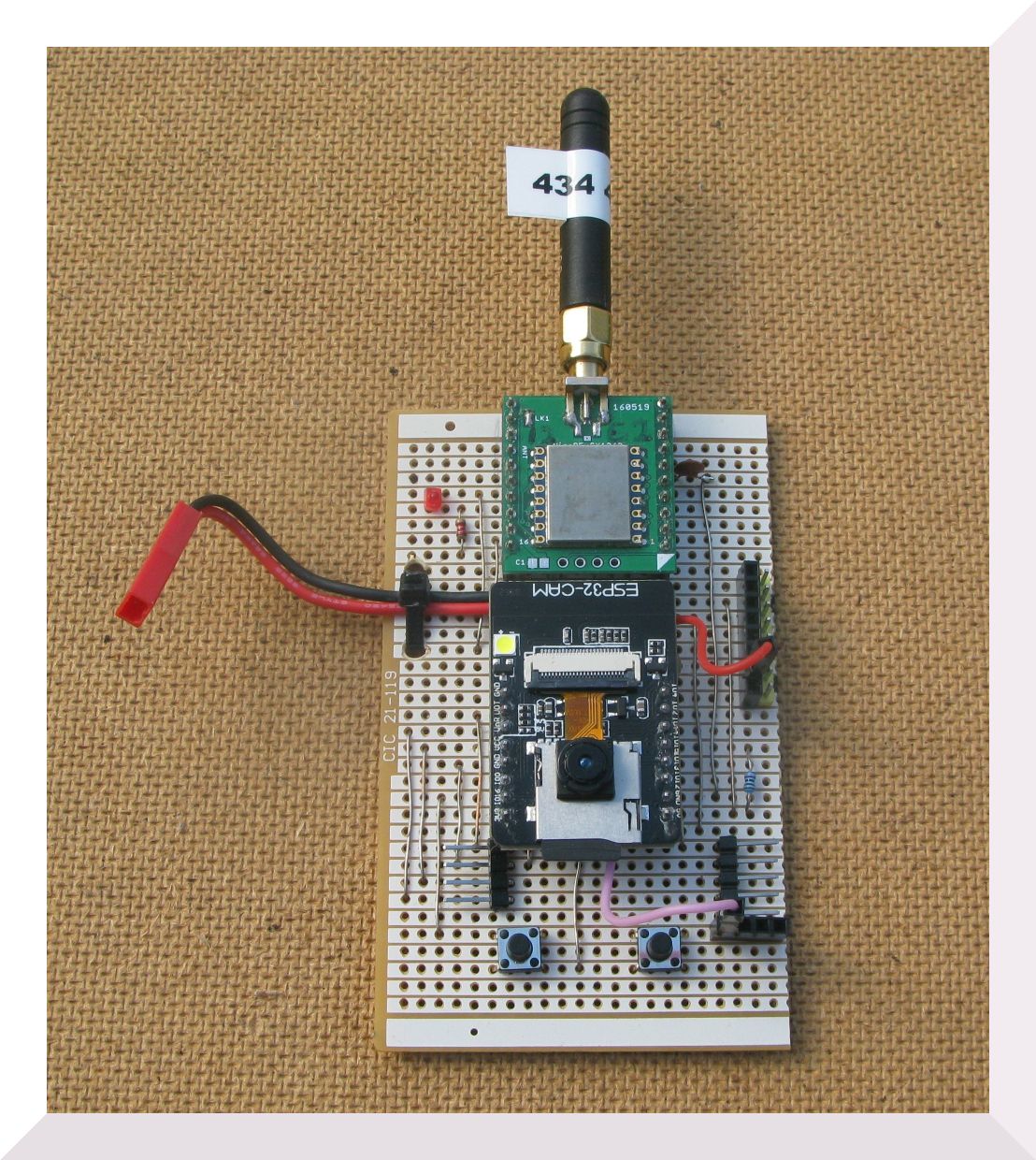
Next I built up a prototype on stripboard so I would have a more robust set-up to test outdoors. I also connected a wire to the output of the on board red LED (pin33) so this pin could then be used for a debugging serial output since the GPS was on the serial program upload port.
So at least you can get the ESP32CAM to take a picture and use a LoRa® device. There is a potential problem here if we want the ability to down load pictures over long distances. At 434Mhz we are normally restricted to a duty cycle of 10%, since for the average SX1278 LoRa® device you need to operate at a bandwidth of 62.5Khz or more. Clearly if your only able to transmit 10% of the time picture download time would be extended. If you could operate at less than 25Khz channels, then 100% duty cycle is allowed (at least it is in the UK).
Operating standard SX1278 LoRa® devices at 20.8Khz bandwidth setting involves manual tuning adjustments at either transmitter or receiver, and it may be that you cannot get communications running at all, so far from ideal. However the SX12XX library being used supports the SX126X devices from NiceRF and Dorji. These devices have TCXOs and are quite happy to work at 20.8khz (or lower) bandwidth with no manual tuning needed. However, the SX126X devices need an extra pin, RFBUSY, and we are already short on pins. The flash LED pin (4) is not really needed so we can connect that to RFBUSY as an input, so does it work ?
It takes only a few seconds to convert the SX1278 program across to SX1262, and this program works too. With RFBUSY being operable, we could also use the SX1280 2.4Ghz LoRa® devices, so fast communications with no duty cycle issues should be possible.
Using pin 4 for RFBUSY does make the pin 4 white ‘flash’ annoying so I removed driver transistor (S8050) that is next to the LED.
The serial programming port needs to be shared between the need to upload programs and reading from the GPS, the TXdata output of the GPS would conflict with the TXdata output from the ESP32. A switch is useful here to disconnect the TXdata output from the GPS whilst a program upload is in progress. Or you could just unplug the GPS.
I set up the program so far to at program restart read characters from the GPS and send them to our pin33 serial debug port. This works so I added the code, examples in the SX12XX library, to read the GPS and wait until it had a fix. The location data was then read and saved and the program carried on taking pictures, saving them to SD and then transmitting the HAB position payload via LoRa®.
It would be important to be able to read the battery voltage, and surprise surprise this is possible by putting a resistor divider on pin 14 that is high enough not to interfere with the use of the SPI interface. The battery voltage is read just after restart before the camera, SD card and LoRa® device are used.
The tracker appeared to be working, but I soon realised it only does so the first time from power up of the SD card. The initialisation and use of the SD card works, but appears to leave the card outputting a high on pin 12 (Data2 pin on SD) and this was being used to read DIO0 from the LoRa® device. With pin 12 high the LoRa® software thinks the device has finished transmitting so the software moves on and the LoRa® transmission is terminated. Fortunately, the TX_Done interrupt from the LoRa® device can be read via a register read so its not strictly necessary to read DIO0 at all. A routine was added to the SX12XX library to cope with this situation and the tracker was fully working. Maybe there is a way of reconfiguring the SD card to turn off that high on Data2, then DIO0 could be read as normal.
I had in mind that it would be possible to read out the memory buffer that was the picture, which is saved to SD, and send it in segments as LoRa®, remote file transfers no less. So I moved the LoRa® transmit to after the picture taking and SD card write, and that worked fine. Maybe file transfer will be possible, one for the future.
The ESP32CAM can be used as a basic tracker and picture taker but I thought it ought to be possible to improve it. For instance add an I2C FRAM for storing the variables such as picture number and maybe last know GPS position, rather than using the EEPROM emulation that uses the relatively low endurance (number of write cycles) of the Flash. Maybe also add a BME280 or TC74 sensor and an IO expander to provide more IO pins. These ideas have been prototyped on the ESP32CAM and do appear to work, a subject of a future blog post perhaps.