The Perils of USB Power Banks
In a previous post: https://stuartsprojects.github.io/2016/04/01/testing-and-comparing-transmitters-receivers-and-antennas.html I described a simple method of testing the relative effectiveness of various transmitters, receivers and antennas, using a series of descending power transmissions, a summary of the technique is below;
Descending Power Tests
Software can be written so that the LoRa® transmitter sends packets starting at one power, reduces the power by 1dBm then sends another packet._
The received packet has the dBm level used for transmit within it so the receiver can record, count and then display how many packets have been received that were sent at a particular power._
With a bit of imagination this simple method of testing can be very useful, we don’t all have easy access to a handy anechoic chamber and expensive signal analysers.
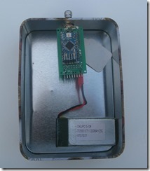
It’s not going to be practical to place the transmitter many kilometres away for testing, however it is possible to significantly attenuate what is emitted from the transmitter by fitting a 50ohm terminator to the antenna socket and putting it all in a tin box with lid on, see picture.

For the tests described here the transmitter was sending packets at bandwidth 62.5Khz, code rate 4:5 and spreading factor 12. The limit of reception at this mode is -20dB below noise level, so a small level of electromagnetic interference (EMI) may disrupt the LoRa® signals. With the transmitter in the tin box as shown and sending packets starting at 17dBm down to 2dBm a receiver fitted with a conventional 434Mhz antenna will pick up packets at 100M or so at an open field and a lot less in a built up area.
Initial Test results
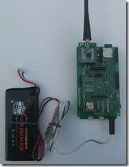
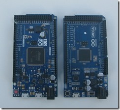
For the initial tests the Arduino base was powered from an external 3S Lithium battery, approximately 12V. I had both an Arduino DUE base and a ATMEGA 2560 3.3V\5V switch-able base.


The transmitter was placed on the far side of my house and the receiver on my workshop bench around 20M away. The position of the receiver antenna was kept consistent throughout.
To show how the tests results can be read take two examples, its not important what the set-ups were. First set-up A and then set-up B, the summary line lists dBm and number of packets received;
Example Set-up A results
Summary 17,22 16,22 15,22 14,20 13,17 12,18 11,7 10,4 9,4 8,2 7,1
You can see that packets from 17dBm down to 12dBm were good then reception tailed off.
I then repeated the test with the same shield, LoRa® module and antenna plugged into an Arduino DUE, the results were slightly worse, reception good down to 14dBm or 13dBm;
Example Set-up B results
Summary 17,17 16,17 15,17 14,13 13,12 12,7 11,4
The conclusion would be that Setup B has an effect on the reception of LoRa® signals, reducing sensitivity by around 2dBm.
To get the printed console output show above I needed the PC USB terminal connected but I was really interested in the performance as a portable receiver. When the transmitter starts its test sequence (at 17dBm) it sends a control packet which causes the receiver to issue a long beep and LED flash. For each packet received it then sends a short beep and LED flash. Thus you only have to count the short beeps to find the limit of performance of a particular setup. Counting the beeps makes outdoor testing easy and this was the method I also used for a 40km hilltop to hilltop test.
Now, if you count the number of beeps for each 17dBm to 2dBm loop you know the limits of sensitivity of each setup. For instance if for subsequent loops of a setup (A) you count 4,5,5,6,5 beeps, the average is 5 so the limit of sensitivity is (17-5)+1 = 13dBm.
If you repeat the test with another setup (B) and the count is 10,9,9,10,10, the average is 9.6 so the limit of sensitivity is (17-9.6)+1 = 8.4dBM. Therefore in approximate terms setup B is 4.6dBm more sensitive than setup A.
Note the tests do not measure absolute sensitivity, but there are a quick and easy way of comparing different setups or hardware to within 1dB performance wise.
Comparing Different Setups
The purpose of this article was first to see if there was a difference in LoRa® performance between the Arduino DUE and ATMEGA 2560 Shield bases and second to check if powering the receiver via an up or down converter affected performance.
Performance of Different Shield bases
The receiver test software will run on either the Arduino DUE or ATMEGA 2560 shield bases with RFM98 or DRF1278F LoRa® modules. The same shield PCB, LoRa® module and antenna were used for all tests.
The first test was with the shield bases powered from a 12.6V 3S Lithium Polymer battery plugged into the shield bases external power input. The results were;
Arduino DUE sensitivity 15dBm
ATMEGA 2560 sensitivity 10.4dBm
So the DUE looses around 4.6dBm when compared with the ATMEGA, and would have only around 60% of the range or distance, this is significant.
Putting the DUE receiver into a metal box reduces the difference between the DUE and ATMEGA receivers to around 1.5dBm, so it is reasonable to assume that most of the noise\EMI is coming in through the antenna.
Using USB Power banks
Initially these appear to be a very good option for powering a portable receiver. They are cheap, plug into the USB port on a shield base and have built in charging and battery protection.

They are normally based on a single Lithium Ion battery so have a boost circuit to provide a 5V output.
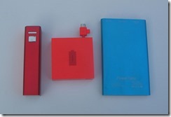
I powered a ATMEAG2560 base from an external 12V battery as before then tried the same test with the power coming from a selection of 3 power banks
External 12V LiPo, sensitivity to 4dBm
Power bank 1, sensitivity to 12dBm
Power bank 2, no reception at 17dBm !
Power bank 3, no reception at 17dBm !
This is a surprising result, although the receiver could receive packets down to 4dBm when powered from an external Lithium battery, there was no reception at all with two of the power banks even for the most powerful 17dBm packets. The conclusion is clear, the 3 power banks tested are not suitable for powering a portable LoRa® receiver.
Conclusions
Avoid power banks for powering portable LoRa® receivers, unless poor performance is acceptable to you.
The Arduino DUE, whilst it is fast, has a worse performance to the slower ATMEGAs.