Testing and comparing transmitters, receivers and antennas.
Many things can affect the performance of a radio link, the location, how far apart the transmitter and receiver are, the way the modules are constructed, battery levels, type of antennas and whether the modules have been damaged or not. At the low power levels used by the LoRa modules, typically 10mW or less, many constructors will not have test equipment capable of measuring such low powers. A similar problem exists for tuning antennas, SWR meters capable of operating at these low powers are not common.
The LoRa modules are capable of measuring the level of signals or noise seen at their antenna input and of carrying out measurements of signal level and noise during packet reception. These measurements may not be to laboratory standard accuracy wise, but they do allow comparative tests to be made. Often a comparative test is sufficient and you can tune an antenna for maximum signal output using a crude signal level meter.
A benchmark test that can be used to check the performance of a pair of 433Mhz LoRa modules or their antennas would also be useful. If its known what the RSSI (signal strength) indication is for a LoRa receiver under a controlled set of test conditions, its possible to establish if a transmitter and receiver pair is working as expected.
A LoRa receiver can be used as a signal strength meter if a LoRa transmitter is used to send data packets. As long as the receiver is at a consistent distance and position in relation to the transmitter, then differences in effectiveness of antennas on the transmitter and receiver will be seen as differences in signal level at the receiver. Also note that the relative differences in received signal strength should equate to relative differences in transmitter or receiver antenna performance. If with a particular antenna the received signal strength increases by 3dB, then that antenna has a relative gain of 3dB, which equates to about 40% extra range performance.
To carry out our standard benchmark test, we need a transmitter and receiver modules loaded with the test software. For the purpose of this test the transmitter has a simple wire antenna, as it would if it was a lost model locator and the receiver has a simple ¼ wave whip made from piano wire. This is an easy build antenna, just solder the length of wire into the pin on a SMA plug intended for assembly onto coax. Insulate the wire from the metal of the plug, the centre of a piece of co-ax is good for this. I have assumed the receiver has been built with a SMA co-ax socket on it. Put a bit of cork on the end of the antenna wire.
All you need now is a large grass field, around 150M across and a can or pole around 1.5M high. Load the transmitter with the test software and secure it to the pole with a bit of tape, see picture. In this case the transmitter test software was program 103_Lora_Transmitter_Detailed_Setup found in Basics examples folder of the SX12XX-LoRa library. The program was set for a transmit power of 10dBm. The LoRa modem settings were bandwidth 125Khz, Spreading Factor 7, Code rate 4:5.
Make sure the transmitter antenna is vertical and straight. For the receiver program you can uses 104_Lora_Receiver_Detailed_Setup if you can use a laptop with a serial monitor to view test results. Its a lot easier to use a receiver that has been built with a display and uses the program 33_LoRa_RSSI_Checker_With_Display found in the Diagnostic_and_Test examples folder.
Walk 50M away from the transmitter and stand sideways to the transmitter so that your body does not act as a reflector and affect the readings.
The receiver will display on monitor and LCD the RSSI, Noise and SNR of the received packets.
Results at 50M for 10dBm (10mW) Transmitter Output Power
I tested two different transmitters, these were the results;
1 TX - Loose 1/4wave wire antenna RSSI -55dBm, SNR +9dB
2 TX - Loose 1/4wave wire antenna RSSI -56dBm, SNR +9dB
I had similar results with a transmitter fitted with a SMA socket and stiff ¼ wave wire antenna.
I confirmed the 10mW output power with the RFExplorer. With an attenuator connected to make sure you don’t blast the input of such a sensitive instrument, the RFExplorer can be used to measure the power output of the LoRa devices.
So there we have it. It should be an easy test for anyone to duplicate, and is a simple way of detecting failed modules. The LoRa modules are prone to damage if operated without an antenna, with these modules the received signal RSSI will be much lower than the -56dBm shown above, maybe in the region of -80dBm or so.
Weakest Received Signals
In a large open field you would need to walk a very long way from the transmitter before signals from the transmitter are so weak that reception is lost. However if you put the transmitter on the ground in an urban area or in a forest, there will be heavy attenuation of the signals and reception will likely fail at between 300M and 1000M from the transmitter. This is not meant to be a test as to what range you will get, that can vary greatly depending on the terrain, all we are doing is attenuating the signals so they are very weak. Walk away from the transmitter till the signals stop being received. The weakest signals received in my tests were;
RSSI -97dBm, Noise –99dBm, SNR –16dB
Expect some variation for your own setups. If there is a lot of RF noise around, the RSSI figure would likely increase as stronger signals are needed to overcome the noise level.
Descending Power Tests
In the tests described so far we have repeatedly transmitted only a single power packet, normally 10dBm.
There is test software program, 10_LoRa_Link_Test_Transmitter, that can be used which starts at one power, sends a packet, reduces the power by 1dBm then sends another packet. In this way you can have the transmitter send packets in sequence from 10dBm to 2dBm or even 20dBm to 2dBm if local regulations permit. The loop can be left to continue for 15 minutes or more and the receiver program is 20_LoRa_Link_Test_Receiver
The descending power test can be used in a variety of ways. It can be used for an easy compare between different receiving antennas for instance. Setup the transmitter to transmit powers from 20dBm to 2dBm. Put the transmitter some distance away from the receiver, and monitor the serial monitor screen in the Arduino IDE for received packets.
The received packet has the dBm level used for transmit appended at the end, this is the Serial monitor output for the test packet at 8dBm;
T*108
The output of the receiver to the Arduino IDE serial monitor looks like this;
696s  +20,RSSI,-131dBm,SNR,-5dB,Length,6,Packets,315,Errors,46,IRQreg,50 (20dBm)
697s  +19,RSSI,-132dBm,SNR,-6dB,Length,6,Packets,316,Errors,46,IRQreg,50 (19dBm)
698s  +18,RSSI,-131dBm,SNR,-6dB,Length,6,Packets,317,Errors,46,IRQreg,50 (18dBm)
699s  +17,RSSI,-132dBm,SNR,-6dB,Length,6,Packets,318,Errors,46,IRQreg,50 (17dBm)
700s  +16,RSSI,-132dBm,SNR,-6dB,Length,6,Packets,319,Errors,46,IRQreg,50 (16dBm)
701s  +15,RSSI,-131dBm,SNR,-5dB,Length,6,Packets,320,Errors,46,IRQreg,50 (15dBm)
702s  +14,RSSI,-133dBm,SNR,-7dB,Length,6,Packets,321,Errors,46,IRQreg,50 (14dBm)
703s  +13,RSSI,-133dBm,SNR,-7dB,Length,6,Packets,322,Errors,46,IRQreg,50 (13dBm)
704s  +12,RSSI,-133dBm,SNR,-7dB,Length,6,Packets,323,Errors,46,IRQreg,50 (12dBm)
706s PacketError,RSSI,-135dBm,SNR,-9dB,Length,6,Packets,323,Errors,47,IRQreg,70,IRQ_HEADER_VALID,IRQ_CRC_ERROR,IRQ_RX_DONE
708s PacketError,RSSI,-135dBm,SNR,-10dB,Length,6,Packets,323,Errors,48,IRQreg,70,IRQ_HEADER_VALID,IRQ_CRC_ERROR,IRQ_RX_DONE
717s  999,RSSI,-129dBm,SNR,-5dB,Length,6,Packets,324,Errors,48,IRQreg,50
End test sequence
Test Packets 324
Test Cycles 30

20dBm,30  19dBm,30  18dBm,30  17dBm,30  16dBm,30  15dBm,30  14dBm,30  13dBm,28  12dBm,27  11dBm,20  10dBm,6  9dBm,1  8dBm,1  7dBm,0  6dBm,0  5dBm,0  4dBm,0  3dBm,0  2dBm,0
CSV,30,30,30,30,30,30,30,28,27,20,6,1,1,0,0,0,0,0,0
Assume that you receive all the packets down to 5dBm and not the lower power ones. You switch to a different receive antenna, and now you only receive the packets down to 8dBm. You then know that (approximately) the first antenna is 3dB better or has 3dB more gain than the second. You can use the same method to check the performance of different builds of receivers.
If when you run the test you receive all packets down to 2dBm, either move the transmitter further away or reduce the transmit power in some way. The easiest way to reduce power transmitted is to use attenuators on a transmitter that has a SMA socket fitted. These attenuators for SMA connectors are readily available, try eBay. Good values of attenuator to have handy are 10dB and 20dB. As an alternative you can cut the transmitted power significantly by fitting a 50ohm SMA terminator (dummy load) on the transmitter output. This can reduce range to a few 10s of metres, especially if the transmitter in put in a metal tin, which can be a useful testing strategy if you don’t have a lot of space.
You can use the test software without a PC as a terminal, which can be handy if your on a remote mountain top. With a UHF hand-held listen for the two start tones that indicate the start of a test sequence on a UHF hand held, or the fast LED flash, and count the LED flashes on the receiver indicating a valid packet received. If the transmitter starts at 10dBm and you count 5 flashes on the receiver, your picking up down to the 6dBm packet. You can make life easier for this type of remote testing if the receivers LED output is replaced by a buzzer.
Test Packet
This is a short packet and uses the first 3 bytes are packettype, destinationnode and sourcenode followed by the power level in dBm as two ASCII bytes, the packet format is thus;
T*108
T= test packet
- = broadcast 1 = from node 1 08 = 8dBm
Test examples
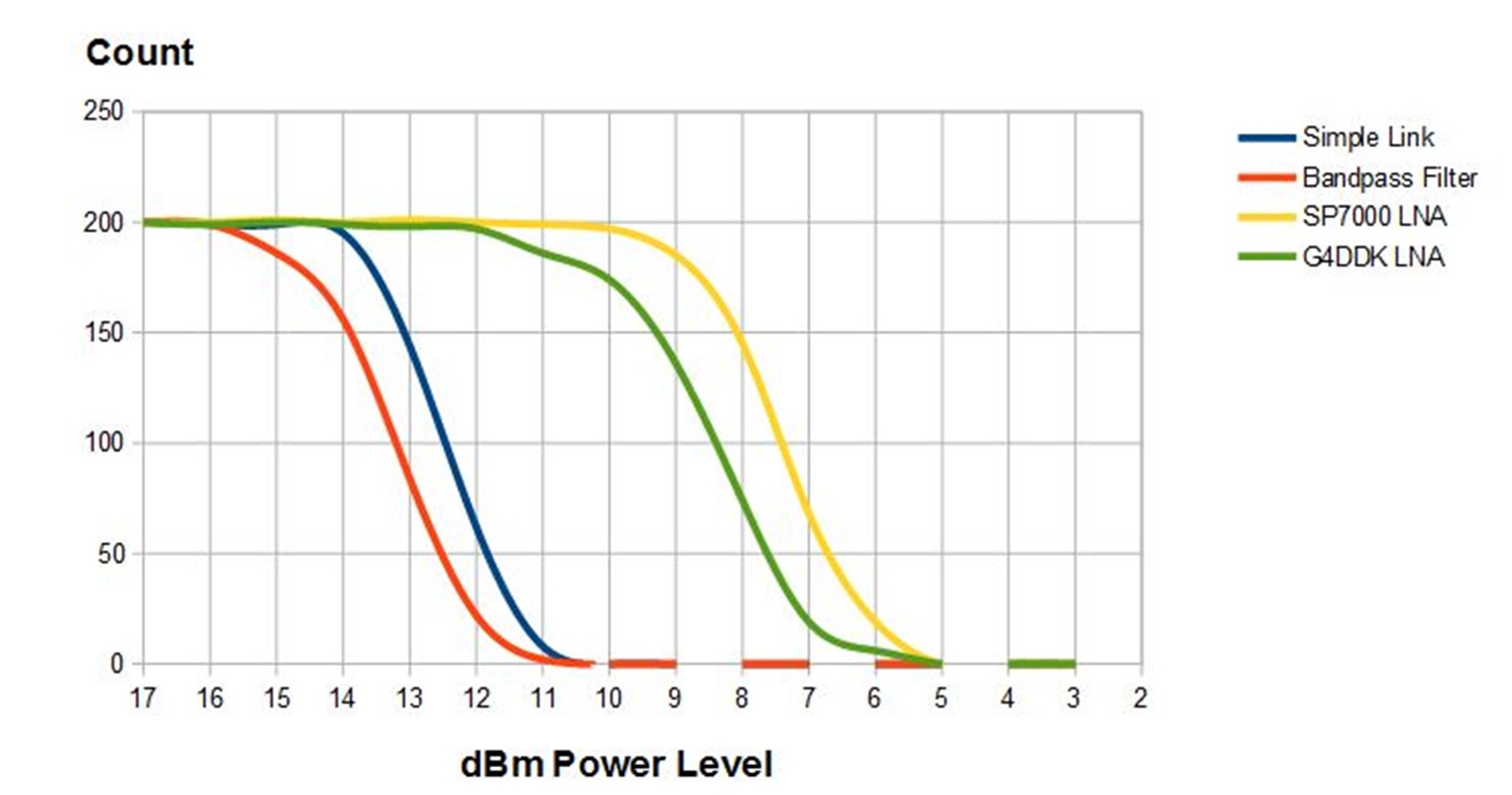
Note that the receiver output above included the counts of the transmit power of each packet that was received, and there is a CSV summary which you can past into a text file, give it a CSV name and import it into a spreadsheet.
Draw a graph of the data and you can see what’s happening. This is an example graph that I produced when I was comparing a standard link, with one that had a bandpass filter added and then two types of LNA were used, an SP7000 and a G4DDK one. The blue line is that standard link and the yellow one the link with the SP7000 added, you can see its clear it added about 5dB useful signal gain.
LoRa Parameters for testing
These are set in both the transmit and receive programs, here are the transmit settings, the LoRa Modem Parameters need to be the same for transmitter and receiver.
//*******  Setup LoRa Test Parameters Here ! ***************

//LoRa Modem Parameters
const uint32_t Frequency = 434000000;       //frequency of transmissions
const uint32_t Offset = 0;                  //offset frequency for calibration purposes

const uint8_t Bandwidth = LORA_BW_125;      //LoRa bandwidth
const uint8_t SpreadingFactor = LORA_SF7;   //LoRa spreading factor
const uint8_t CodeRate = LORA_CR_4_5;       //LoRa coding rate
const uint8_t Optimisation = LDRO_AUTO;     //low data rate optimisation setting

const int8_t TXpower = 17;                  //Transmit power used when sending packet starting test sequence
const int8_t start_power = 17;              //link test starts at this transmit power
const int8_t end_power = 2;                 //and ends at this power
const uint8_t ThisNode = 'T';               //this identifies the node in transmissions
The full list of Bandwidth, Spreading Factor, Coding rates and data rate optimisation settings used is is found in library file SX127XLT_Definitions.h (for SX127X devices) , and reproduced here;
//Constant names for bandwidth settings
#define LORA_BW_500  144  //actual 500000hz
#define LORA_BW_250  128  //actual 250000hz
#define LORA_BW_125  112  //actual 125000hz
#define LORA_BW_062  96   //actual  62500hz
#define LORA_BW_041  80   //actual  41670hz
#define LORA_BW_031  64   //actual  31250hz
#define LORA_BW_020  48   //actual  20830hz
#define LORA_BW_015  32   //actual  15630hz
#define LORA_BW_010  16   //actual  10420hz
#define LORA_BW_007  0//actual   7810hz

//Constant names for spreading factors
#define LORA_SF6 0x06
#define LORA_SF7 0x07
#define LORA_SF8 0x08
#define LORA_SF9 0x09
#define LORA_SF100x0A
#define LORA_SF110x0B
#define LORA_SF120x0C

//Constant names for coding rates
#define LORA_CR_4_5  0x02
#define LORA_CR_4_6  0x04
#define LORA_CR_4_7  0x06
#define LORA_CR_4_8  0x08