LR2021 FLRC 2600 Distance Test and Data Logging
The fastest FLRC that the LR2021 can produce is with a BandwidthBitrate setting of 2600, which has an on-air data rate equivalent to 1,950Kbps. It would be helpful for comparison purposes to have an indication of how far the line of sight range would be for that mode.
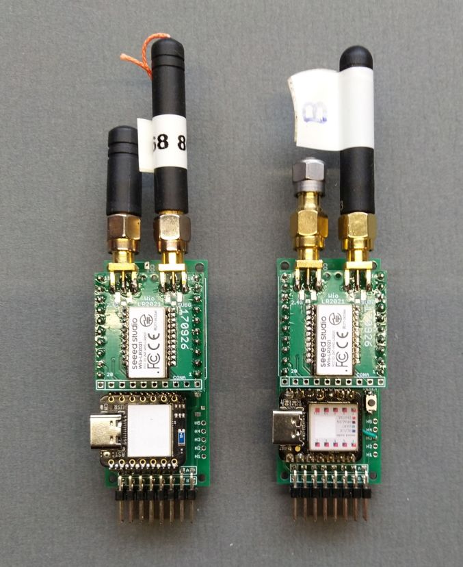
So I carried out a distance ping test with the transmitter set to -9dBm transmit power and with a 10dB attenuator in line with the antenna, this means the actual radiated power was -19dBm.
I used the same small stubby antennas used for the previous tests and the distance at which reception stopped for the 2600 FLRC was 163M.
In a previous test, which was for the slowest FLRC (195Kbps) I had used a 20dB antenna attenuator and the maximum distance of packet reception was then 185M. This is close to the 163M of this new test on the fastest 2600 FLRC.
So the since the tests used the same devices and antennas this suggests an approximate 10dBm difference in sensitivity between the fastest and slowest FLRC. This is in line with the LR2021 datasheet specification;
FLRC_2600_CR05_915_S Sensitivity 1% PER 915 MHz = -100.5 dBm
FLRC_260_CR05_915_S Sensitivity 1% PER 915 MHz = -111 dBm
So what distance does the reduced power fast 2600 FLRC test equate to if full module power was used and the antenna attenuator was removed ?
Fortunately the attenuation of RF signals follows some basic rules. If you want to double the distance your signals go you need to use 4 times the power. 3dB is double the power so 4 times the power is 6dB. The figures to keep in your head for the relationship of distance to dB are;
- 6dB 2 x distance
- 10dB 3.16 x distance
- 20dB 10 x distance (10dB + 10dB = 3.16 x 3.16 = 10)
So for the LR2021 if we increase the transmit power from the minimum used in the test to the maximum possible so -9dBm to 22dbm, that is a power increase of 31dBm, which equates to a distance increase of 35.48 times as in;
(the square root of (10 raised to the power of 3.1)).
Removing the 10dB antenna attenuator would further increase distance by 3.16.
So by switching to full power and no antenna attenuator we might expect the range\distance to increase to;
35.48 x 3.16 x 163M = 18,275M
That is a result, 18Km, which may be a surprise but remember that line of sight distances can be many many times what we get in urban or forest\vegitation areas.
To confirm that 18Km is possible then clearly some form of direct comparison is needed, possibly a line of sight test over several kilometers with no antenna attenuators and probably some better antennas.
The antennas I used for the test were short stubby ones. These are not high gain antennas but for comparison tests that does not matter, as long as you always use the same antennas. From some previous tests I know that bigger better antennas would add a few dB gain to the transmitter and receiver antenna.
Simple data logging
If your carrying out testing of RF devices its often useful to record the results of the tests. For instance if one of the XIAO boards is being used as an LR2021 receiver then the program code is probably sending the results of the tests to the Serial monitor which you can then view if the board is connected via the program port to a PC or Laptop;
130s,FLRC04058,RSSI,-49dBm,Length,10,Packets,94,Errors,0
131s,FLRC04059,RSSI,-49dBm,Length,10,Packets,95,Errors,0
133s,FLRC04060,RSSI,-49dBm,Length,10,Packets,96,Errors,0
But for field testing we really want to keep EMI generators such as PCs and Laptops away from the devices being tested. If the XIAO had an SD card then you could also save the above text direct onto a file on the SD card. However its a lot easier to use a board called an Openlog. The OpenLog is a small low cost board that can log data received over a serial port.
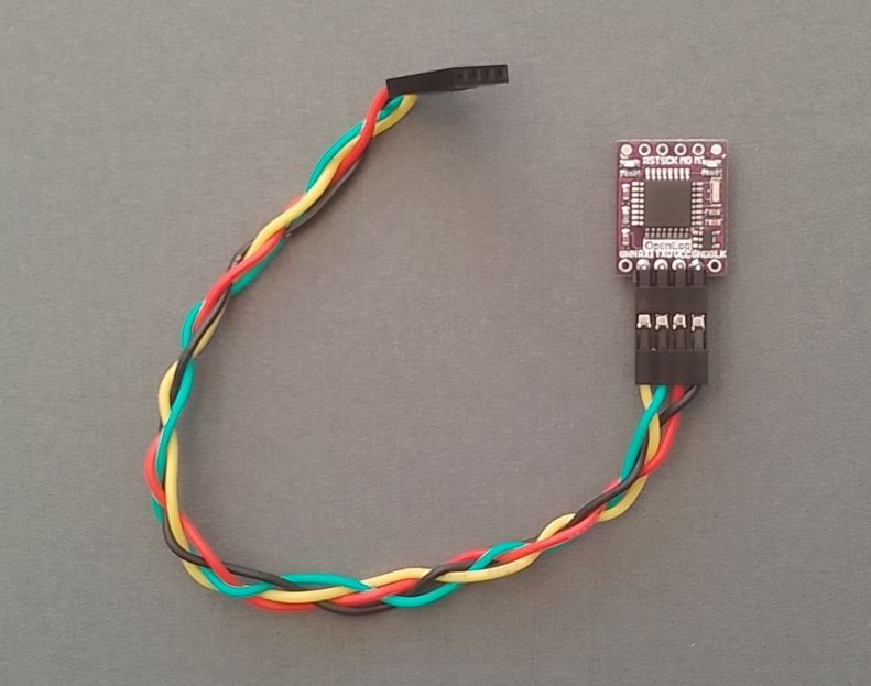
Now a XIAO has two serial ports, one is on the main programming port (Serial) and the other is on the D6 and D7 pins (Serial1).
Normally a program would send serial output to the default programming port like this;
void packet_is_OK() {
  Serial.print(F("Transmitted > "));
  Serial.print((char*)TXbuffer);
  Serial.print(F(",Power,"));
If all the Serial.print() commands are changed to mySerial() like this;
void packet_is_OK() {
  mySerial.print(F("Transmitted > "));
  mySerial.print((char*)TXbuffer);
  mySerial.print(F(",Power,"));
And in the programs board file (that defines the pins used) you add this;
//Serial port definition
#define mySerial Serial  //use Serial to send Serial output to USB
                         //connector, to use the XIAO Serial port
                         //pins on D6 and D7 use Serial1
Then the #define mySerial Serial would cause all the Serial output to go to the standard USB Serial port. Change the define to #define mySerial Serial1 and all the Serial output will go to the Serial1 port on pins D6 and D7 of the XIAO. If you then plug the Openlog into the D6\D7 pins all the programs Serial output, as in test results, will be recorded onto an SD card file.
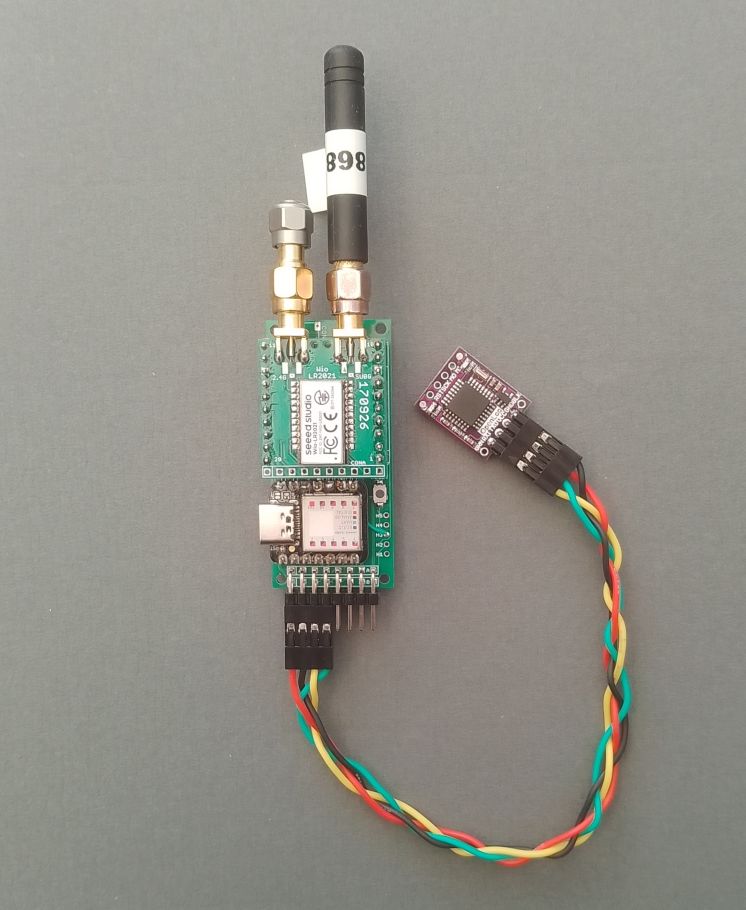
Note that the test programs I have published use a Serial baud rate of 115200 and the Openlog defaults to a 9600 baud rate. To change it to 115200 baud load the config.txt file that will be found on the openlogs SD card and change the 9600 to 115200 as below;
115200,26,3,0,1,1,0
baud,escape,esc#,mode,verb,echo,ignoreRX
Each time the Openlog is powered up it starts a new log file name.