Improved LoRa Camera - Part 2
Displaying Images
The receiver software used in the previous ESP32CAM project stored the received image on an SD card and if the receiver was connected via the serial terminal to a PC it could then transfer the images to a folder on the PC. Whilst this allowed the received pictures to be quickly viewed it would be helpful if the images could be received and viewed on a hand held portable device with no PC required.
There is an Arduino library that allows downloaded JPGs to be re-sized and displayed on a colour TFT display. Thus for viewing received images you would not be limited to viewing only 320x240 images which is a typical TFT display size.
However the use of a TFT display now creates a new issue for the image receiver, we potentially have 3 SPI devices in use, LoRa, SD card and the TFT display.
Sharing SPI SD card with other SPI devices
I did try having the SD card running in SPI mode on the same bus as the LoRa device, but this would fail for some SD cards. Some SD cards would simply refuse to initialise, some SDs would fail at a point in the future or the LoRa module would hang. The SD card also appeared to fail more readily when used in a deep sleep camera application.
Fortunately the ESP32S3 supports the use of the SD card in 3 pin MMC mode so there is no need to run the SD card on the same SPI bus as the LoRa and TFT display.
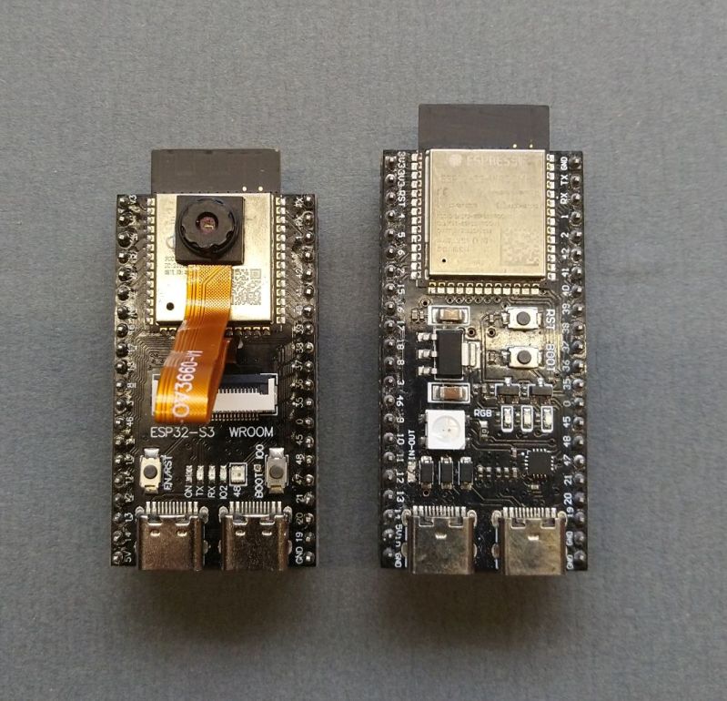
Improving the LoRa camera needed a PCB that connected a LoRa device and TFT display to SPI buses and with the SD card connected in MMC mode. The ESP32S3 Development board would seem ideal for the processor, plenty of GPIO pins together with the possibility of using WiFi to transfer images and Bluetooth to monitor the transfer process.
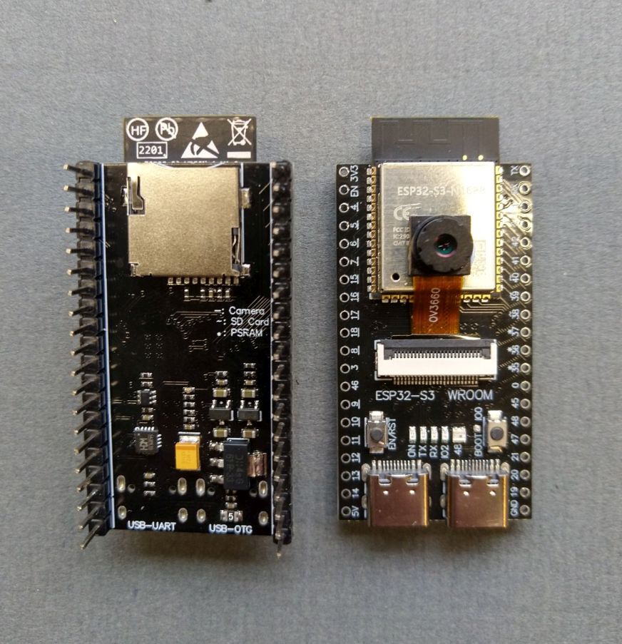
The ESP32S3 Camera Development board is very similar, it uses the same pinout as the plain development board with the addition of a camera connector on top and SD card holder underneath.
Both types of ESP32S3 Development board are shown below.
I first produced a PCB for the ESP32S3 Development boards in mid 2025 and it allowed me to try the various combinations of SPI bus sharing for the LoRa, SD card and TFT display.
Receiver PCB Design
After a fair bit of testing of the various combinations I came to the conclusion that the SD card would be used in MMC mode and the LoRa device and TFT display would be on the two SPI buses that the ESP32S3 has available.
The ESP32S3 Camera Development board uses 14 GPIOs for the camera so without the camera there are then plenty of spare GPIOs for the receivers TFT display. A PCB design that would use the ESP32S3 Camera Development board for the camera node and the plain ESP32S3 Development board for the receiver node was easily possible as the device pinouts are almost identical.
The up to date 050426 version of the receiver PCB looks like this;
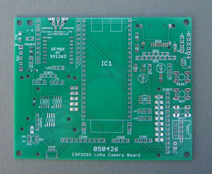
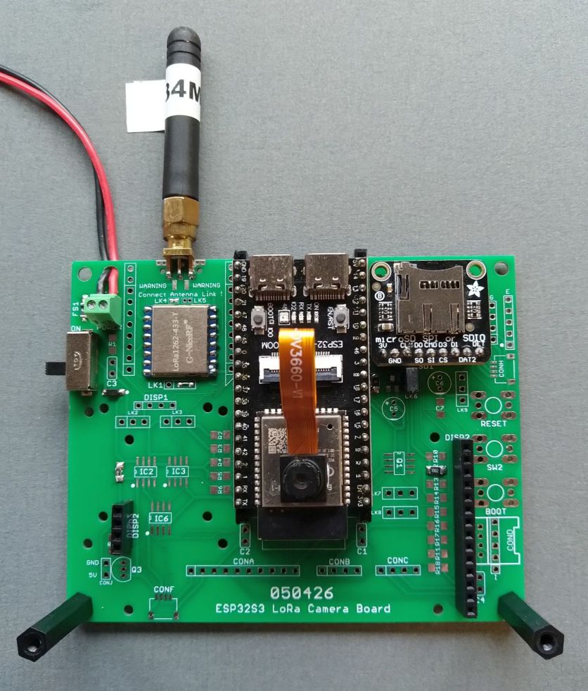
The PCB above can also be used in camera mode and is pictured below on the left in camera mode and in receiver mode with display on the right.
![]()
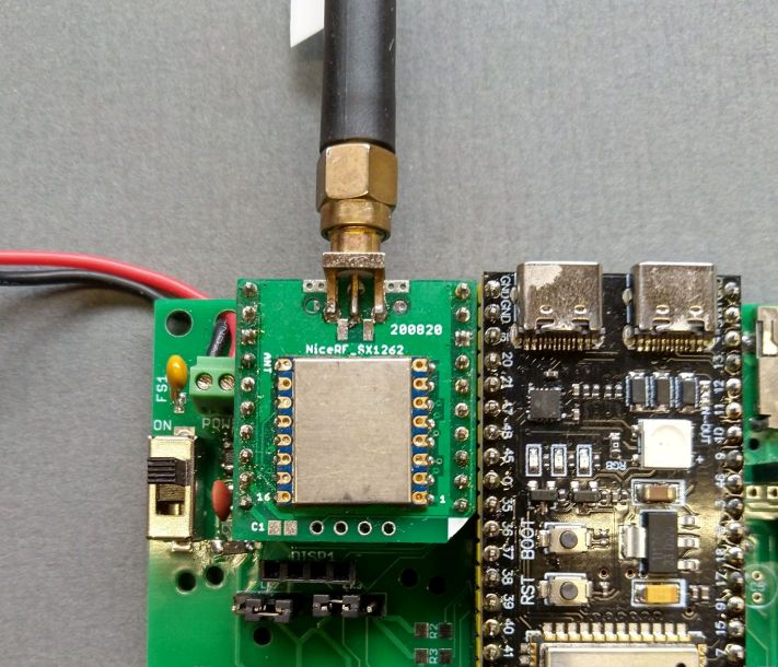
The PCB has pads to fit a bare LoRa module, Hope RFM9X, Nice RF SX1262 on the front of the PCB or an NiceRF SX1280 on the rear of the PCB. There are also pads for a Mikrobus compatible socket that can take the plug in LoRa modules I often use. An example of a LoRa module on a Mikrobus compatible board is shown below;
The PCB was designed in Eagle CAD and the design files and Gerbers are available for general use and can be found here;
https://github.com/StuartsProjects/Devices/tree/master/Improved%20LoRa%20Camera
Kicad is able to import the Eagle PCB files.
The ESP32S3 Camera Development board does have a SD socket in MMC mode on its bottom side, see picture below on the left;
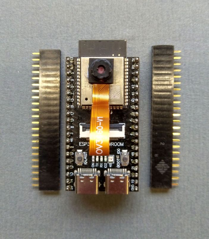
It can be awkward to access this SD socket if the development board is mounted flush to the PCB on pin headers. If the ESP32S3 Camera board is mounted on the PCB with pin header sockets (see below) then it is a lot easier to access the SD card socket under the ESP32S3 board.
Reliability wise its best to use the SD socket on the underneath of the PCB with the modification described above. If you wish you can fit SD card holders to the PCB on the right of the ESP32S3 module. There is a choice of an SMT SD card holder, a breakout board with 6 way 0.1” pins or an Adafruit Micro SD board.
The non-camera ESP32S3 Development Board does not have a SD card holder underneath so you need to add one to the PCB. The SMT SD card holder is the best choice.
The 050426 PCB can be fitted with an INA219 to monitor the battery supply voltage and current. There are also connectors for I2C and QWICC boards, GPS, and HC05\HC06 Bluetooth module. For the camera transmitter you can fit a small OLED display which you could use to report what the camera is doing.
The 050426 PCB is 100mm x 80mm and I have used it as a remote camera. However a camera PCB does not need room for a display so a more compact remote camera PCB can be made.
Compact Remote Camera PCB
The compact camera 120426 PCB I designed for the remote camera is below;
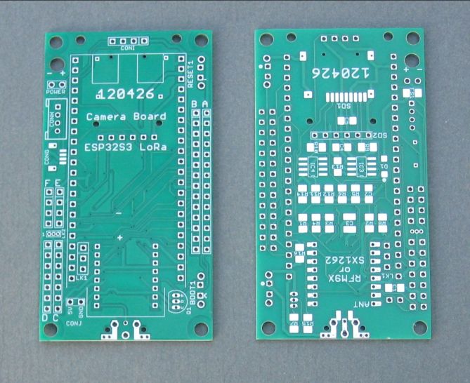
And the PCB assembled as a camera is below;
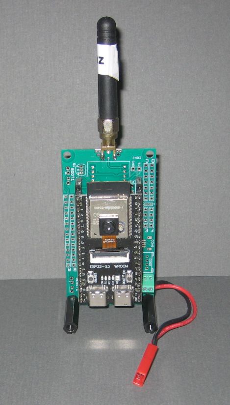
For this smaller camera PCB the LoRa module can be a Hope RFM95 or Nice RF SX1262 and is mounted on the rear of the PCB. A version of the PCB for the SX1280 will be designed in future.
I won’t put a full description or assembly instructions of the PCBs shown above in this article but will add these to the device repository at a later date.
Check out the schematics of the PCBs in the device repository for more details;
https://github.com/StuartsProjects/Devices/tree/master/Improved%20LoRa%20Camera
ESP32S3 camera development board sleep currents
The ESP32S3 Camera Development board does not have a specific connection for a battery so the battery was connected via a diode to the boards 5V pin. Through this battery connection you can measure the current consumption of the camera PCBs, but do remove the USB connection.
Deep Sleep
The bare bones ESP32S3 camera development board, with no camera or SD card and not plugged into the PCB, has a deep sleep current of 4mA, which is quite high. However there are some power saving measures that can be done.
If you have SMT assembly skills you can change the boards AMS1117 regulator to the same pinout AP7361 regulator, this reduces the deep sleep current by 1.5mA to 2.46mA. You can remove the boards green power LED and the blue IO2 LED, this reduces the sleep current to 0.55mA. Looking real good.
If you add the camera and SD card and use the power save options then the sleep current is 0.65mA. Don’t use a OV2640 camera as it cannot be put into a low power standby with the camera transmitter software.
A sleep current of 0.65mA makes a battery powered remote wake up and take pictures camera possible, solar powered maybe.
Light Sleep
Using the same power save options as for deep sleep described above the light sleep current of the board is 1.87mA.
LoRa Camera Image Transfer Application
I have been working on the new image transfer application for some time and needed the improved PCBs described above to make the new software work.
You can program the camera board, place it in a location, top of a post or tree for instance and control and re-configure the LoRa settings the camera uses from the receiver.
When the camera wakes up from deep sleep, it initialises the PSRAM, Camera, SD card and LoRa device and then broadcasts a ready message using fixed long range LoRa settings. The receiver defaults to listening on the same set of long range LoRa settings. The receiver can be setup to receive from a particular camera number, 1 to 255 or listen for any camera when the listen camera number is set to 0.
The camera transmitters ready broadcast as default contains the LoRa settings to be used by the receiver for the actual image transfer. For example this is part of the code that writes the LoRa settings to the ready broadcast packet;
LoRa.writeUint32(var.Frequency);
LoRa.writeUint8(var.SpreadingFactor);
LoRa.writeUint8(var.Bandwidth);
LoRa.writeUint8(var.CodeRate);
You will note that the variables are members of a structure, var. A structure is used for the program variables so that there is the option of saving the program settings as a block in the ESP32S3 Flash Store. Saving the variables as a store in Flash then allows the settings of the camera transmitter to be changed remotely and then saved in Flash for permanent use.
The initial values of the variables such as var.Frequency are found in the ConfigSettings.h file that is part of the transmitter and receive programs, for example;
uint32_t Frequency = 434000000; //Frequency of transmissions in hertz
Receiver Serial Configuration Menus
The receiver has a series of serial menus to configure the settings used by the camera transmitter which you can access by connecting the board via the programming USB cable to a PC using a serial terminal application such as TeraTerm. Its also possible to use an Android phone or tablet to connect via the USB connection or Bluetooth as the receiver PCB has pin connections for a HC06 or HC06 Bluetooth board.
With the receiver running and connected to a serial terminal application enter a character on the keyboard and the receiver will stop listening and display the menu below;
Change Settings
---------------
1 LoRa settings
2 Camera settings
3 Request image download
4 Program settings
5 Erase receiver store
6 Update receiver store
7 Erase transmitter (camera) store
8 Update transmitter (camera) store

P Print settings
U Use changes
X Exit
Here you can change the LoRa settings to use (for the image transfer) set which camera to listen for (1 to 255) or request an image download number.
You can make changes and use them once. If the changes work make them again and select the menu option to update the receiver or transmitter (camera) store.
Sleep period issues
The program code as supplied has a default deep sleep period for the camera of 60 seconds. You can change this period via the receiver serial menu. If the camera is in deep sleep you cannot wake it up with the current software. To make changes to the transfer settings you need to wait for the camera transmitter to wake from deep sleep and transmit its ready broadcast.
The transfer programs provided are an initial design and one change due shortly is to have the cameras LoRa device awake in permanent listen mode so that you can request an image at any time. The standard LoRa listen mode is not adequate as the current used is around 7mA which is a bit too much for battery operation. A very low current listen mode feature is not immediately possible since it requires a change to the SX12xx-LoRa library.
Flash store of settings
The initial program settings for both the receiver and transmitter are in the ConfigSettings.h file which is part of the program files.
To allow the active settings to survive power downs, resets and deep sleep wake ups the active settings can be saved in a Flash store. The serial menus in the receiver (see below) allow the receiver to save its own setting to Flash store and send a command for the camera transmitter to save its current settings to its Flash store. Without the specific requests to save the settings to Flash store the program defaults will be used. The Flash stores can be erased which cause the respective device to revert to the inital program settings stored in the **ConfigSettings.h **file.
At startup from sleep the camera transmitter checks that the structure (with the program settings) stored in Flash is valid and if it is copies the structure across to the running var structure in RAM. This might all sound a little long winded but it does allow the settings the camera transmitter is using to be permanently changed without having to retrieve the camera transmitter and physically re-programming it. The receiver uses a similar store which is checked at reset and power up.
The transmitter and receiver will switch to the LoRa settings contained in the ready broadcast the camera sends on wakeup unless you have asked the receiver to make changes.
Camera default operation
The default operation of the camera transmitter will be found in the programs ConfigSettings.h file. The camera and receiver will work with these settings assuming the receiver is within range of the transmitter.
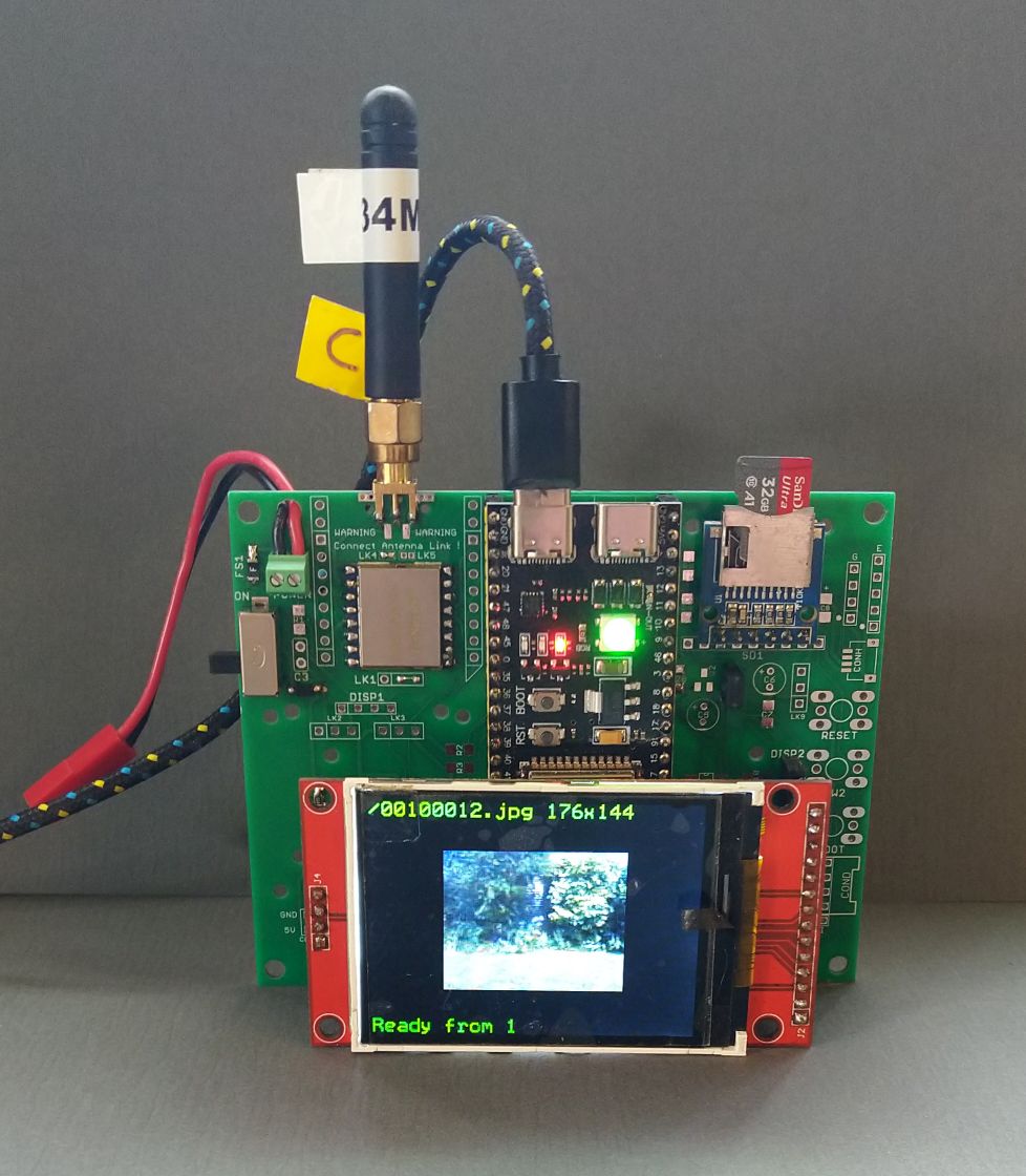
Whilst the settings for the image transfer can be changed on the receiver via the serial menus they can be left at the initial programmed defaults and the receiver should work, displaying and saving images to SD with no intervention. The initial interaction of the transmitter and receiver is at a set of long range LoRa settings so the receiver should be displaying ‘Ready from 1’ when it receives the ready broadcast from the number 1 camera transmitter. The transfer settings by default are at the fastest the LoRa modules can do so if image transfer appears to start but does not complete try reducing the effective speed of the LoRa settings.
The primary LoRa settings that govern the transfer speed are the Spreading Factor (SF5 to SF12) the bandwidth (500Khz to 7.8Khz) and coding rate (4:5 to (4:8).
The fastest, shortest range\distance settings would be SF5, bandwidth 500Khz and coding rate 4:5. The slowest longest range\distance settings would be SF12, bandwidth 7.8Khz and coding rate 4:8. The range\distance difference between the fastest and slowest setting would be circa 30 to 100 times. The LoRa serial menus on the receiver will prompt you for the valid settings for spreading factor, bandwidth and coding rate.
The camera transmitter default is at each wakeup to take 3 pictures. The first 2 pictures are taken at the image size defined by var.StandardImageSize and saved to SD card. The camera then takes the third image at the size defined by var.SentImageSize and this is then the image transferred via LoRa. The intention here is that there are two images taken at a high resolution, say 1600x1200 and that the transferred image is then a lower resolution say 160x120. This ‘thumbnail’ image will transfer a lot quicker. The idea here is that the receiver will display the thumbnail image and if it looks interesting then you can send a request to the camera to transfer one of the higher resolution images.
The image sizes available on the OV3660 and OV5640 cameras are;
FRAMESIZE_UXGA // 1600 x 1200
FRAMESIZE_SXGA // 1280 x 1024
FRAMESIZE_HD   // 1280 x 720
FRAMESIZE_XGA  // 1024 x 768
FRAMESIZE_SVGA // 800 x 600
FRAMESIZE_VGA  // 640 x 480
FRAMESIZE_HVGA // 480 x 320
FRAMESIZE_CIF  // 352 x 288
FRAMESIZE_CIF  // 400 x 296
FRAMESIZE_QVGA // 320 x 240
FRAMESIZE_240X240  // 240 x 240
FRAMESIZE_HQVGA// 240 x 176
FRAMESIZE_QCIF // 176 x 144
FRAMESIZE_QQVGA// 160 x 120
FRAMESIZE_96X96// 96 x 96

// 3MP Sensors
FRAMESIZE_FHD  // 1920 x 1080
FRAMESIZE_P_HD // 720 x 1280
FRAMESIZE_P_3MP// 864 x 1536
FRAMESIZE_QXGA // 2048 x 1536

// 5MP Sensors
FRAMESIZE_QHD  // 2560 x 1440
FRAMESIZE_WQXGA// 2560 x 1600
FRAMESIZE_P_FHD// 1080 x 1920
FRAMESIZE_QSXGA// 2560 x 1920
The receiver will save the transferred image to SD, work out the resolution, shrink it if required and display it on the TFT display. The shrinking is needed since the transferred image could be 1600x1200 pixels which cannot directly be displayed on the 320x240 TFT display.
Image Numbering
Images taken by a camera are numbered from 1 to 65535, 1 is the number used at reset and is increased for each image taken. The file names for images are formed as such;
/CCCNNNNN.jpg
Where CCC is the camera number, 1 to 255 and NNNNN is the number of the image, 1 to 65535.
So if the camera is number 1 and the image number is 10 the filename used is;
/00100010.jpg
Programs
The working programs for the camera transmitter and receiver are;
1_LoRa_Remote_Camera_Transmitter
2_LoRa_Remote_Camera_Receiver
And will be found in the ‘ESP32S3 LoRa Camera Programs’ folder at the project device repository;
https://github.com/StuartsProjects/Devices/tree/master/Improved%20LoRa%20Camera
Next:
Camera with Low Current LoRa Permanent Listening.
Connecting the Receiver to an Android device.