Improved LoRa Camera - Part 1
The original ESP32CAM board is a small and low cost camera board and in a previous project I developed code to allow the transfer of the images to a remote receiver with LoRa. That Arduino code will be found in the SX12XX-LoRa library here; https://github.com/StuartsProjects/SX12XX-LoRa. The ESP32 processor used on the ESP32CAM is, when the camera and SD card are connected, critically short of spare GPIOs. This causes quite a bit of difficulty when also trying to use a LoRa device. To get the ESP32CAM camera and SD code to work with LoRa it was necessary to restart the ESP32 via a deep sleep every time you needed to take a picture and then initialise and use the SD card and LoRa device in a particular sequence. Using light sleep would be an advantage for some applications but it was not practical due to the requirement to stop and start the devices to cope with the lack of pins. Using the LoRa radio for other purposes, remote control of the camera for instance was also not very practical. Plus there are no spare GPIO pins on the ESP32CAM if you wanted to add sensors or a GPS.
It would be an improvement if the devices in use on the camera board, camera, SD card and LoRa device were on independent GPIO pins so that they could be freely used. Also the remote camera would be more flexible if it were possible to add sensors and\or a GPS.
ESP32S3 Camera Development board
There is now an ESP32S3 based development board that has a camera and SD card connector. The board is pictured below;
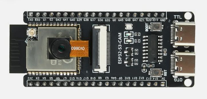
The camera used on this development board is an OV2640, OV3660 or OV5640. When the camera and SD card are in use the board has 9 free GPIOs, plus two of the strapping pins could be used with care.
The use of these ESP32S3 camera boards with the extra GPIO pins meant that the original ESP32CAM LoRa image transfer code could be improved significantly to allow remote control of the LoRa camera since once the LoRa device was initialised it could be left running. If the LoRa camera is placed in a remote location then its useful to have a mechanism for changing the LoRa parameters used for the actual image transfer. Faster LoRa settings would allow for lower power usage of the camera but until the camera is in position you cannot know which are the fastest LoRa settings that are going to work in a particular location.
Full flexible LoRa two way comms would also allow for the selective downloading of images from a particular camera. To save time and power you might have the camera take a high resolution image followed by a much lower resolution one that would be quicker to transfer. If the low res image looks interesting you could send a request to the remote camera to download the full high res image.
Issues with SD card
One of the concerns I had when testing the ESP32S3 camera development board is that there were some issues when the SD card was on the same SPI bus as the LoRa device. The dev board itself does have an SD card holder and its used in MMC mode, which is the same as the ESP32CAM.
I needed an application that would test the ESP32S3 camera development board as a functioning camera, it would take pictures, save them to SD card and record any errors found. You could connect the ESP32S3 camera development board up to a powerbank and leave it running long term in order to test the reliability.
Stand-alone camera application
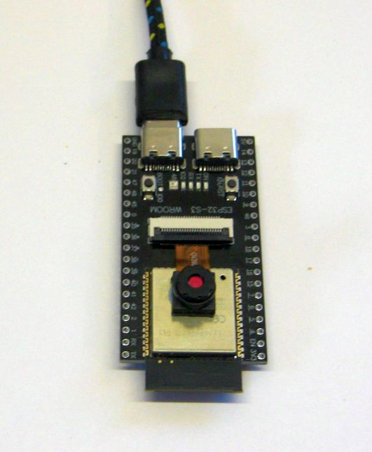
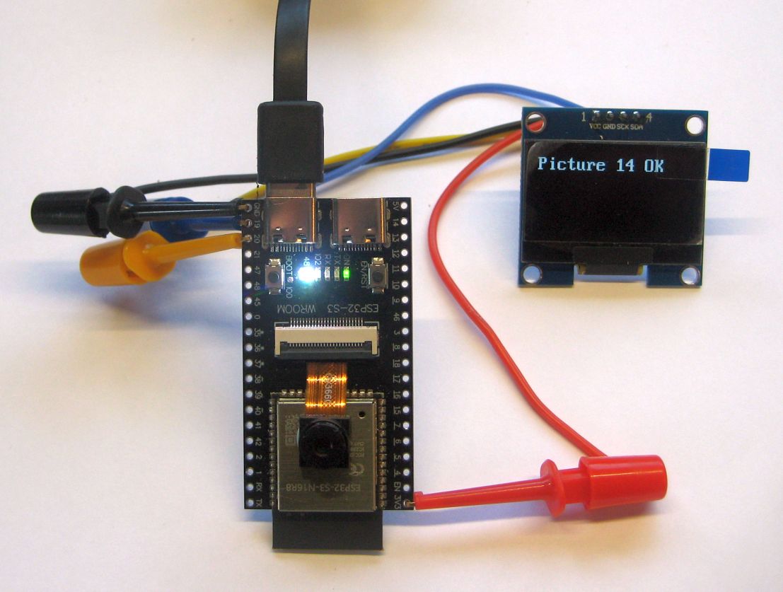
The program I wrote is a stand-alone camera application for the ESP32S3 camera development board, it puts the ESP32S3 into a low current deep sleep and when it wakes up, it flashes the on board neopixel LED as white, takes pictures and saves them to SD. The program records errors and posts them to the Serial monitor and\or an OLED display. If an error is found then the neopixel LED turns red. If you leave the camera connected via USB to a PC you can log the serial monitor output, which includes any errors found, to a PC text file with a PC application such as Teraterm. The picture below is the board connected to a PC and running as a complete stand-alone camera.
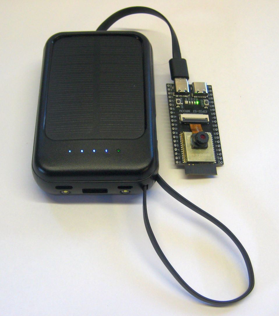
If you want to use the board as a simple remote camera, then power it from a USB solar power bank;
Note that there are two USB connectors on the ESP32S3 camera development board, one is a native USB port on GPIO pins 19 and 20, the other is a standard CH343 serial UART connection which uploads programs and sends serial terminal output to GPIO pins 43 and 44. The programs I wrote for the ESP32S3 board assume the CH343 USB port is used and this then potentially frees up IO19 an IO20 to be used as an I2C port.
To monitor a remote boards activity and check back for potential errors you can connect an Openlog device to the ESP32S3 serial transmit pin, (IO43) so that the openlog records all the serial output. The Openlog is a simple Atmel processor based board that reads incoming serial data and saves it to a log file on an SD card, a very useful device.
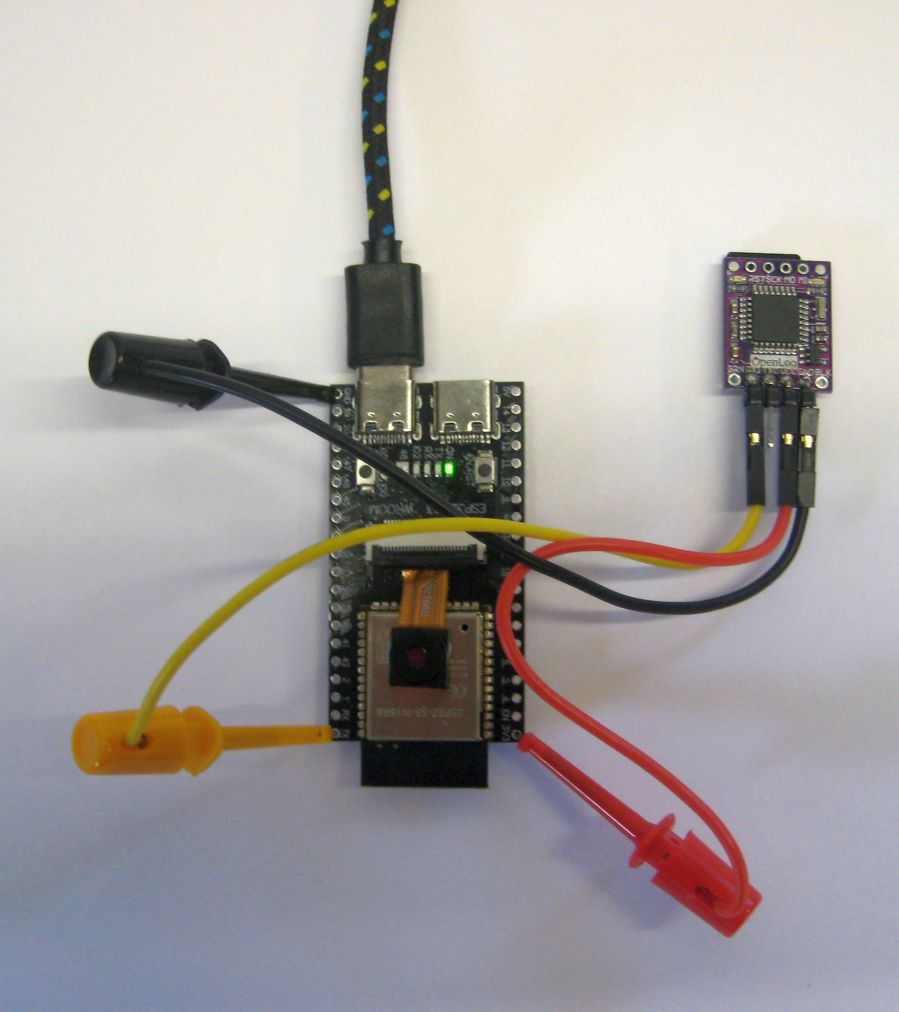
Or you can connect an SSD1306 or SH1106 OLED to the I2C pins used, SDA is IO19 and SCL is IO20. The OLED displays the number of pictures taken and a sum total of any errors found.
The software for testing the ESP32S3 camera development board can be found here;
https://github.com/StuartsProjects/Devices/tree/master/Improved%20LoRa%20Camera
Note that the 2_Take_Picture_Save_to_SD_DeepSleep program in the repository above is the program for a basic stand-alone camera powered by a USB powerbank.
Next: Need to design a PCB to take the LoRa device.