Improved Tracker and Sensor Node for XIAO and LoRa
This is an upgraded version of the original Board_for_XIAO_LoRa. Its known by its part number 020123.
When testing the original board as a TTN or LoRaWAN sensor it became clear that for a more reliable and compliant node which was using deep sleep functions to preserve battery power together with the preferred OTAA (over the air authentication) connection to TTN then the node would need to save authentication parameters in a non volatile memory.
The XIAO SAMD21 has no EEPROM so the Board_for_XIAO_LoRa layout was changed to take a FRAM. This is a surface mount part, but easy to solder. The board length only increased from 39mm to 41mm.
Some other small changes were made;
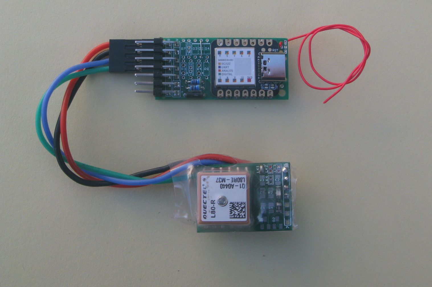
Swapped the positions of ConA and ConB so that one of my GPS boards could be connected directly to the end of the PCB.
Made it easier to allow the resistor divider that can be fitted to the A0 pin to monitor the incoming battery voltage. Added the option of some pullups that might be needed on other versions of the XIAO to keep deep sleep current low. There are locations for a couple of 1.8mm LEDs.
The FRAM is not needed for GPS trackers or sensor nodes. There are example programs in the board repository intended to help you test the board as its being built. This test as you go approach, is far better than trying to figure out what the problem may be on a finished board that does not work.
Within the device repository there are working examples for a GPS tracker and receiver;
20_GPS_Tracker_Transmitter
21_GPS_Tracker_Receiver_With_Display
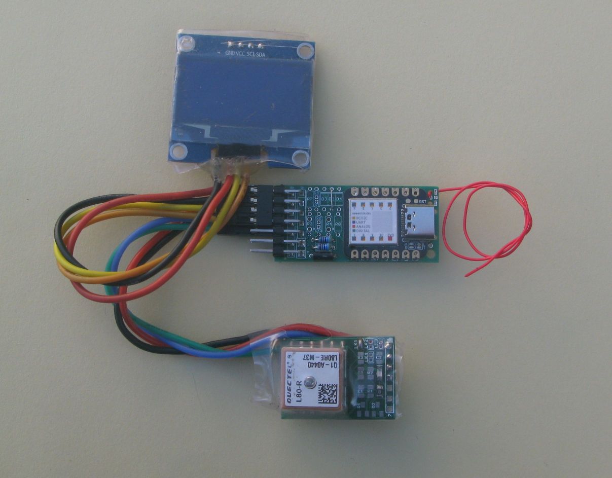
If the receiver above has a GPS attached, it will display the distance and direction to the transmitter.
There are examples for a sensor node that uses a BME280 temperature, pressure and humidity sensor to send readings long distances with LoRa. The sensor is well suited to long term battery operating as it can be put to sleep for long periods and the battery current used is only 5uA, when the XIAO green power LED is removed.
22_BME280_Sensor_Transmitter
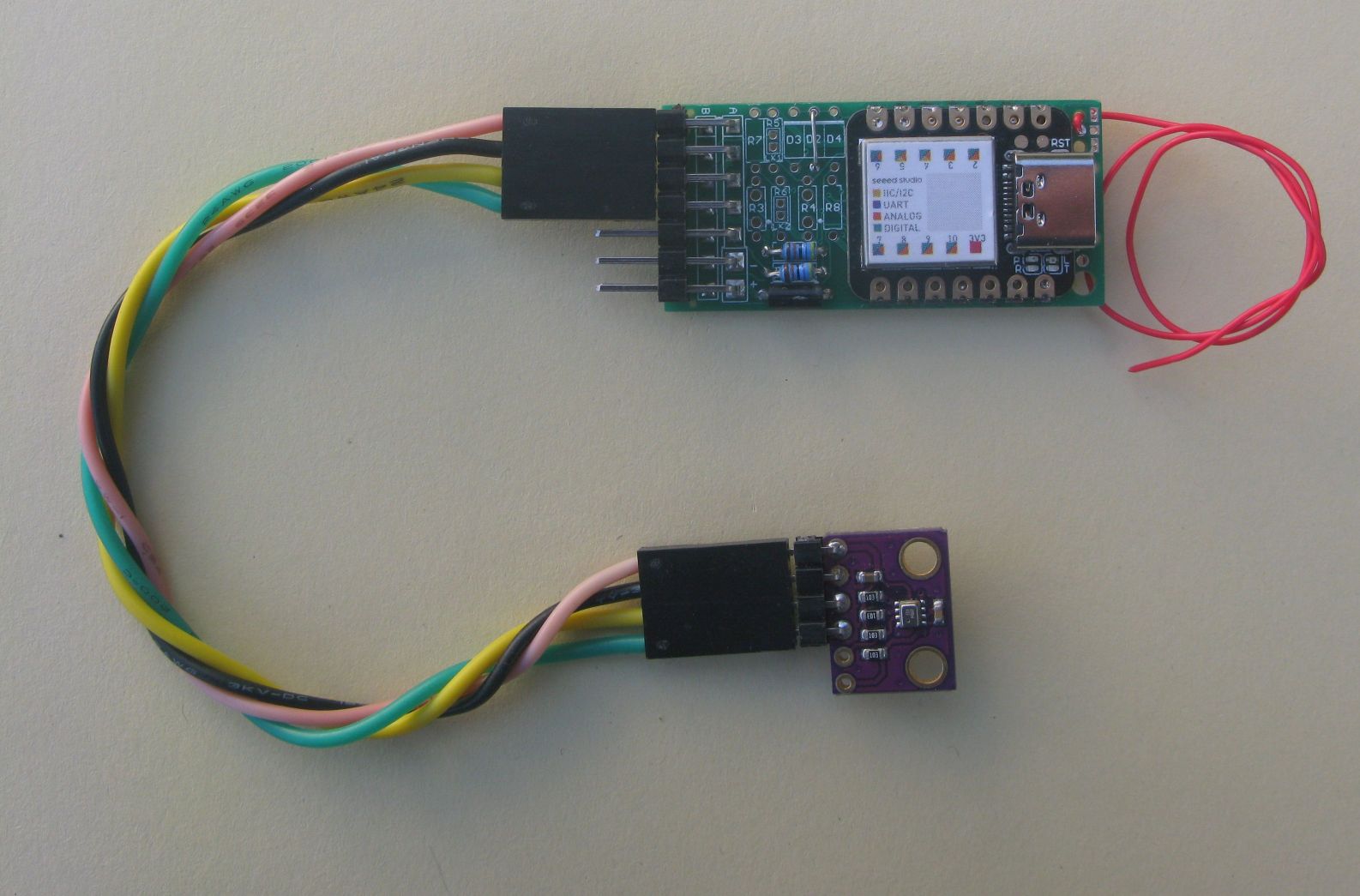
23_BME280_Sensor_Receiver_With_Display
The purpose behind Board for XIAO LoRa
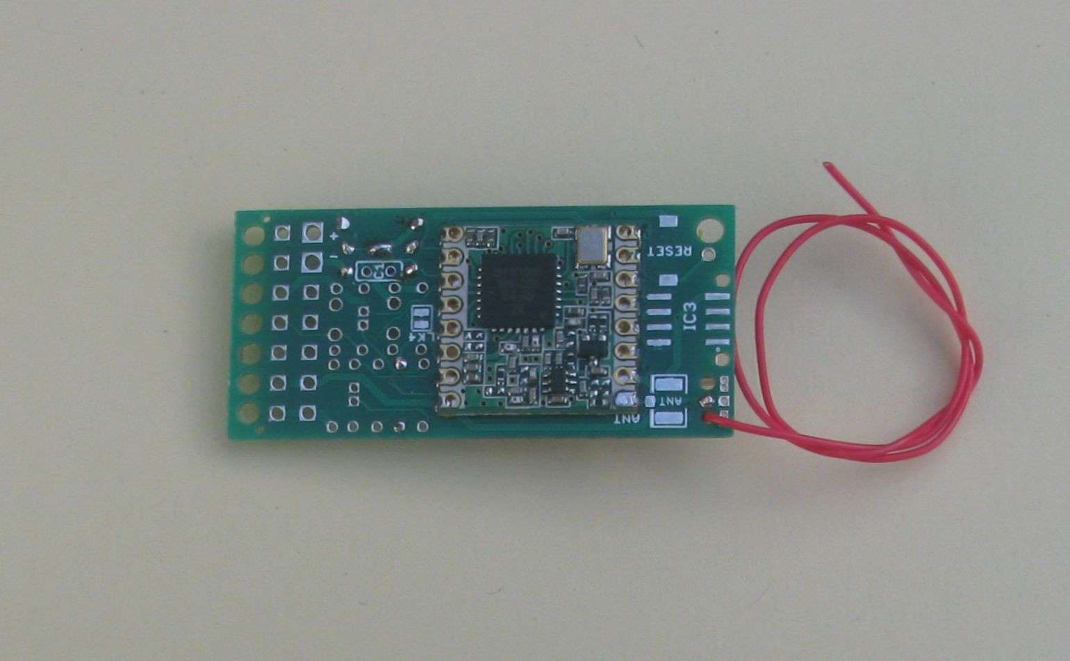
A recent project to use a LoRa radio as a range extender for a Cycle disturbance alarm had me building a small (37mm x 16mm) Atmega328P based board with a RFM95 LoRa module. A GPS module could be added to end of that board so it could function as a long distance LoRa tracker. To get the board small and light it needed to use small surface mount components. Fine for me to assemble, but building the board would not be within the capability of a lot of people. You needed to order and acquire a good number of parts too, very time consuming.
The XIAO SAMD21 offered a potential solution, especially as I found that if the green power LED was removed, the deep sleep current went down to around 5uA. This XIAO has an internal RTC (real time clock) that could be used to put the board into very low current sleep for extended periods. The XIAO is also very small, around the same size as a typical LoRa module. The XIAO and LoRa module have large pads and are fairly easy to solder.
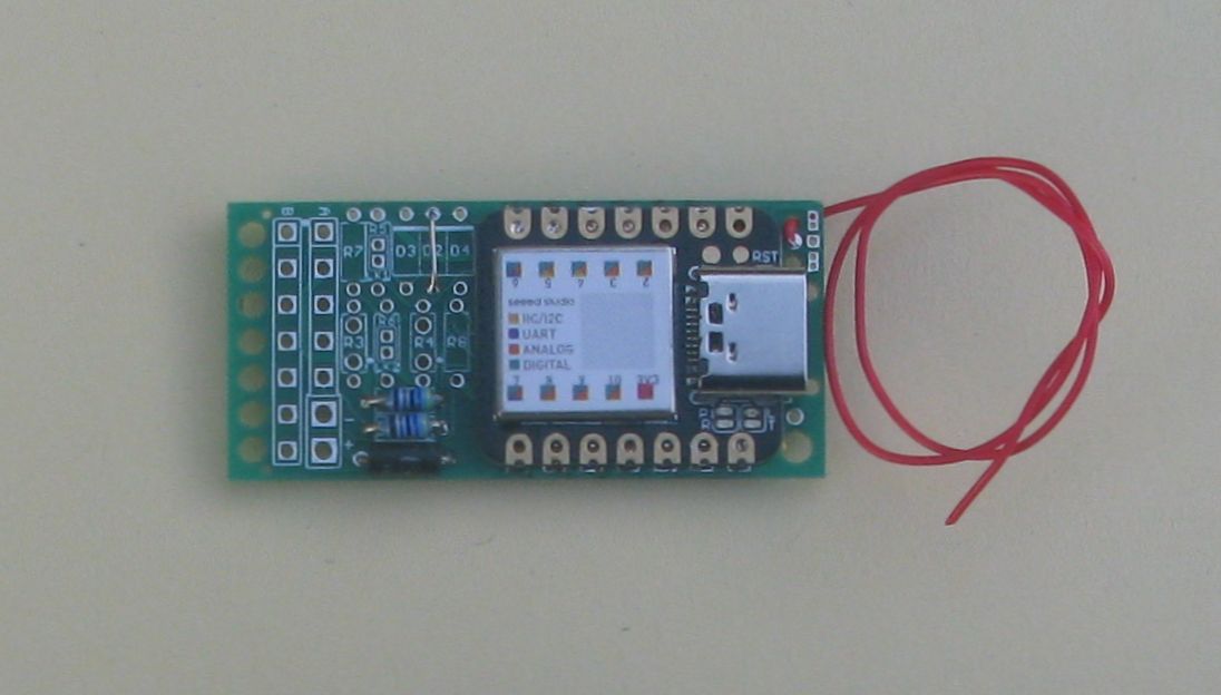
Using (small) surface mount components for such a small tracker or sensor node would be the normal design choice, but I specifically wanted the board to be very easy to assemble. So I used small wired components instead. The resistors are the 125mW (1/8Watt) versions which are easy to find. Despite using wired components the board is still quite small however, only 41mm x 19mm. Considering the board space taken up by the XIAO and LoRa modules and the need to connect an external GPS or I2C sensor the board would not be significantly smaller even if 0603 SMT parts had been used. It would probably only be about 5mm shorter.
With this board you can get it working with only a few parts. You just need the board, battery, some wire, an XIAO, RFM95 and a sensor or GPS and you have a working sensor node or GPS tracker. This board would also be a good fit for the cycle alarm range extender and most people with basic soldering skills could assemble it.
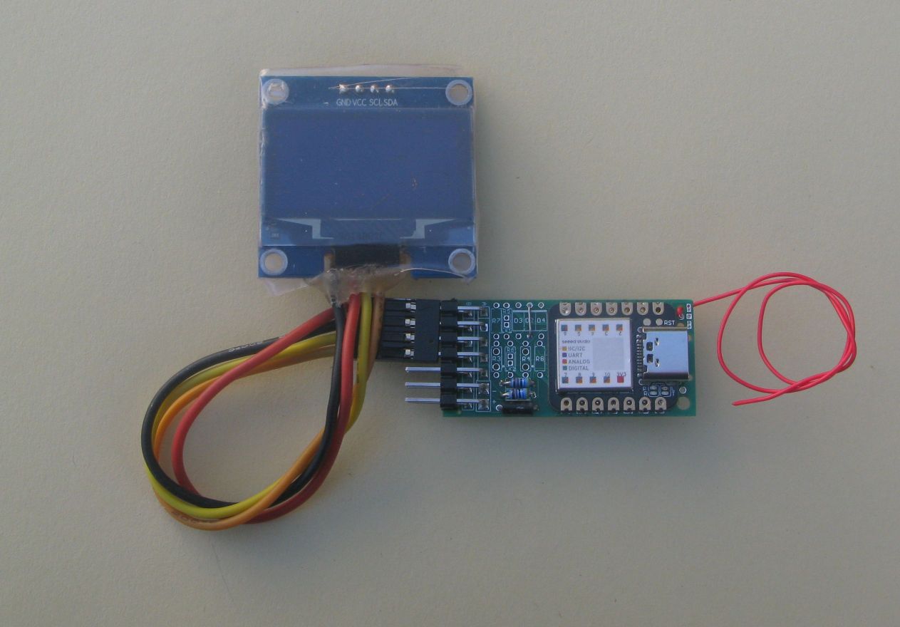
The XIAO does not have a lot of IO pins however, only 11. So with the SPI interface for the LoRa module needing pins for SCK,MOSI,MISO,NSS,NRESET and DIO0 there is not many pins left. If you use another pin for a resistor divider to read battery voltage, then there are now 4 pins left. Lets say 2 for the serial on a GPS and 2 for an I2C sensor and all the pins are gone. Fortunately a lot of sensors do just need an I2C interface and power. I2C displays are common too. If you want more pins then you could add an I2C IO expanders or I2C devices that have their own analogue voltage read pins.
This is not a board for running a nuclear power station, but it does have enough pins and connections to be used as a small GPS tracker, either ground based or high altitude balloon, or as a TTN or LoRaWAN sensor node.
Weights
Seeeduino XIAO SAMD21 2.06g
RFM95 LoRa module 0.73g
Bare PCB weight 1.25g.
Built board weight, XIAO and LoRa module with wire antenna and components to read supply voltage is 4.67g. Adding a Quectel L70 GPS takes the weight of a land based or high altitude balloon tracker to 6.06g + battery of choice.
The Board
The board files in Eagle PCB format can be found in this device repository;
The device repository also has example programs, build instructions and layout diagrams.
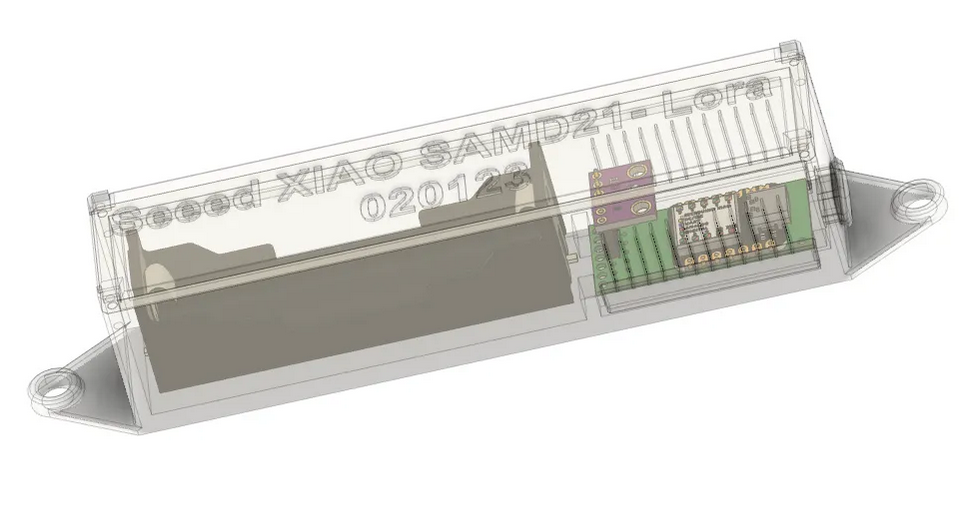
Enclosure
Netweaver has produced a model for a printing an enclosure for the board and a 18650 Lithium battery, you can down load it here;
https://www.printables.com/model/400065-stuartprojects-loraseeed-xiao-samd21-fram-pcb-v2-1