Easy Build TTN and LoRaWAN Nodes
My recent adventures with the Seeeduino XIAO SAMD21 had me thinking that it could be used to make a very easy to build sensor node for TTN. Basically the node could be made using only these parts;
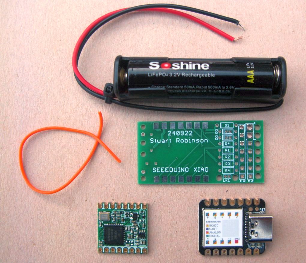
Add a sensor of choice, which could be a simple switch or an I2C temperature and humidity sensor such as the BME280.
With the XIAO green power LED removed (easy to do) the assembled board has a deep sleep current of 4.5uA, which is good for a long battery life.
Sensor power usage
For a typical TTN sensor node we first need to consider battery life. If your monitoring the temperature of a remote greenhouse for instance, you dont want to be visiting every few days to replace batteries.
The normal running or idle current of the XIAO SAMD21 is in the order of 12mA. A battery of 3 x AAA Alkalines is small and low cost with a capacity of circa 1000mAhr. Unfortunately with an idle current of 12mA the battery would only last 3.5 days, a bit less because of the power used by transmissions. This short battery life is a problem.
A lot of remote sensors do not need to transmit very often, say once an hour if you were monitoring the temperature in the greenhouse for instance. For each sensor reading the actual time a sensor needs to be active, reading the sensor and transmitting the information, is typically less than 10 seconds, thus there are 3,590 seconds in every hour when the sensor is doing nothing at all really.
Power used for a transmission
If the node during the 10 seconds it is awake, sends a packet for TTN that is sent at SF8 it will have an air time of 150ms. The transmit current is typically 90ma so the power used would be 0.15 x 90 = 13.5mAsecs. The idle current for the 10 seconds awake would be 12mA x 10 = 120mAsecs. So total power used, for each sensor reading and transmission is 133.5mAsecs.
The XIAO (with green power LED removed) was tested with a LoRa device and the sleep or shut-down current was 4.5uA. So assuming we send the sensor data every hour the total mA seconds used in a day and using sleep\shut-down mode is;
133.5maSecs + (3,590 x 0.0045) = 149.65mAsecs an hour or 3,592 mAsecs per day.
Now 3,600mAsecs is the same as 1mAhr, so if we can implement the sub 5uA sleep mode the node will use only 1mAhr per day. This would extend the battery life of the pack of AAAs from 3.5 days to around 3 years, a very worthwhile improvement.
So sleep mode is very good for battery powered sensors. However there is a problem that affects the LMIC libraries for TTN in particular and that problem is legal duty cycle restrictions.
Legal Duty Cycle
TTN and other LoRaWAN sensors mostly operate in frequency bands where no device license for the transmissions is needed. To allow the limited frequencies available to be shared by large numbers of users each device is limited to how long it can transmit for. Mostly with TTN applications this duty cycle limit is 1%. So if you have a packet that has an air time of 100mS you can only send that packet once every 10 seconds. The LMIC libraries for TTN\LoRaWAN impose this duty cycle limit. The library code records the time the last packet was sent and knows the air time of the packets, so when you request to send another packet it will wait the duty cycle time from when the last packet was sent before it sends the next packet. This limiting can go unnoticed at low spreading factors where the packets have a low air time. However consider what happens when the node is a long distance from the nearest gateway and consequently a large LoRa spreading factor is in use.
At spreading factor 12 a packet might have an air time of two seconds thus there is a legal duty cycle limit of one packet transmission every 200 seconds. This limit is in itself not an issue since we probably only want to send the packet once an hour.
However going back to the problem of powering nodes from batteries, for long battery life we really do need to put our node into deep sleep for long periods.
The LMIC libraries use the processors internal clocks for timing, and these clocks almost always are stopped during deep sleep and they only start again when the node is woken from sleep. Thus when the node wakes up from say a one hour sleep the LMIC internal timing does not know the node has been asleep for an hour since the processor clocks that do the timing dont run in sleep mode.
When you then try to transmit a packet, after the one hour deep sleep, the LMIC library timings think you have only just sent a packet and the code will therefore wait the duty cycle limit before the packet is actually sent. This means that from the wakeup point the node may spend 200 seconds in idle mode (thinking it is imposing the duty cycle limit) before it sends another packet and this is very bad for battery life.
We can work out the effect of this apparent duty cycle limit; the node now spends 200 seconds every hour running at 12mA;
200secs x 12mA = 2,400mAsecs = 0.67mAhr.
So with 24 transmissions a day this false imposition of duty cycle costs us around 16mAhr of battery capacity, battery life on the AAAs would be 62 days.
LMIC_low_power library
There is a version of LMIC that sought to address this problem (of false duty cycle imposition) and allow the running program to update the timer that LMIC uses in order to allow for the sleep times;
https://github.com/CongducPham/LMIC\_low\_power
The LMIC_low_power library code modifies (in hal.cpp) the way hal_ticks() returns the LMIC timing from this
uint32_t scaled = micros() » US_PER_OSTICK_EXPONENT;
to this;
uint32_t scaled = (micros()+os_cumulated_sleep_time_in_seconds*1000000) » US_PER_OSTICK_EXPONENT;
The variable os_cumulated_sleep_time_in_seconds can be updated from the primary sketch. So just after a deep sleep, the variable os_cumulated_sleep_time_in_seconds is updated with the sleep seconds and the LMIC scheduler will think that time had advanced by those seconds since the last transmission, so no duty cycle wait would be needed.
Long sleep periods
This change to the hal.cpp code did appear to work when the sleep periods were short, say 10 minutes, but if you wanted to apply a longer wait, say 4,100 seconds which is about the shortest interval at SF12 to be sure to be within the TTN fair use access limit, then problems occurred, every other wake up would result in a long wakeup of several minutes.
There is mention in the LMIC_low_power library of os_cumulated_sleep_time_in_seconds*1000000 having a circa 4295sec roll-over, which may well have been the cause of the problem.
I thought about this for a while, clearly problems could occur if two, four,twenty four hour or longer deeps sleeps were needed.
Then I was struck by the obvious. The LMIC node and library code does not need to know if the sleep corrections are for an hour or even longer periods. To prevent the library code enforcing a duty cycle wait, all it needs to be told is that the time has advanced a little bit more than the required duty cycle wait. The longest packet there should be at SF12 has around a 2.4 second air time, so 240 seconds (assuming 1% duty cycle) ought to be the longest period the LMIC library would need to wait to enforce duty cycle. With code changed to set 240 seconds as the update period to os_cumulated_sleep_time_in_seconds, but with a separate processor deep sleep time of 3600 seconds, there were no issues noticed over several days of operation of a node, awake times were in the order of 7-10 seconds only. So total awake time for a day would be 240 seconds or so.
Reliability of SAMD21 deep sleep wakeup
I have seen comment that the SAMD21 can on occasion lock-up coming out of deep sleep. This was using the standard Arduino SAMD21 compatible cores which is different to the core that Seeeduino produce for the XIAO.
Rather than wait weeks or years to see if a node could reliably come out of deep sleep, I decided to speed up the testing process by using a very short deep sleep interval. When in deep sleep, the processor timers are stopped and only the low power RTC timer is running. Thus you would expect the code and processes the processor uses to go into deep sleep mode and to come out of it back to normal running, would be similar for a one hour sleep as it would be for a one second sleep.
RTCZero deep sleep
Some deep sleep code for the SAMD21 uses the RTC via the RTCZero library to set a wakeup alarm some time in the future. In this mode the sleep current is around 5uA. The code for a one hour deep sleep looks like this;
rtc.setTime(0, 0, 0);

rtc.setAlarmTime(1, 0, 0 );  //set alarm for 1 hour

rtc.enableAlarm(rtc.MATCH_HHMMSS);
I set the sleep down to 2 seconds and using my own LoRa library I programmed the node to send a 32 bit counter as a packet, incrementing at each send, and sent at bandwidth 500khz. This gave the packet an air time of 7mS so at 1% duty cycle I could send the packet every 700mS. Another node was programmed to receive the packet and copy the counter to the serial port so I could keep an eye on how many packets, and thus deep sleep wake ups, there had been.
The node ran for over 25,000+ deeps sleeps, there were no lock-ups.
ArduinoLowPower deep sleep
The LowPower.sleep(sleepmS); command from the ArduinoLowPower.h library is an easy way to do deep sleeps, no need to set up the current time and alarm time through the RTC library. With the LowPower.sleep(sleepmS) function used on the XIAO SAMD21, the sleep current is around 5uA so the same as using the RTC.
Using the ArduinoLowPower.h library for deep sleep the node ran for over 50,000+ deeps sleeps, again there were no lock-ups.
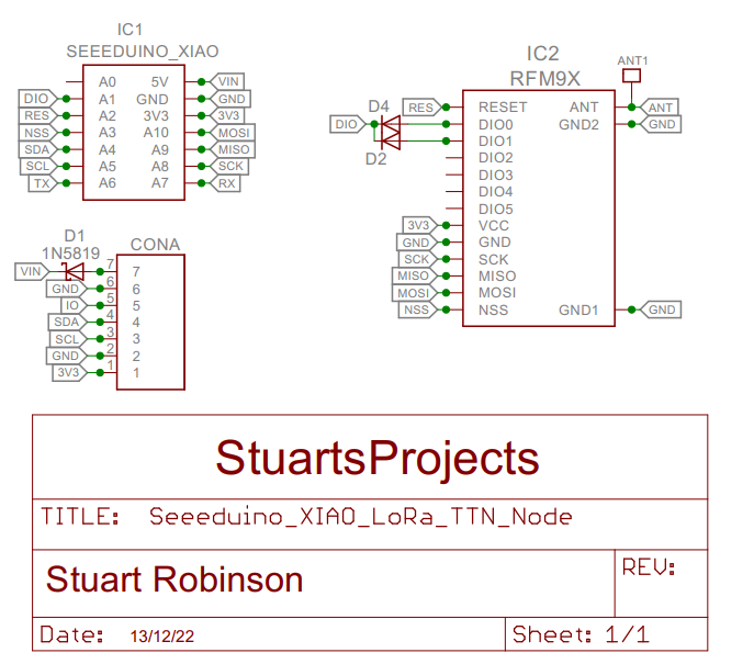
Board Schematic
The components needed for the TTN node are very minimal, basically just the XIAO on the front of the board and the LoRa module on the back. Diodes D2 and D4 allow the TTN sketch to read the LoRa modules DIO0 and DIO1 on the same XIAO pin. D1 protects the board agianst reverse supply.
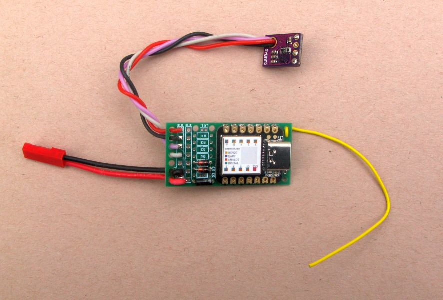
Built board
This is what the built board looks like. You could use pin headers to connect up the BME280 I2C sensor, but the holes in the end of the board next to the solder pads can be used as strain reliefs, so only wires are needed.
TTN - LoRaWAN Sketch
The changes to the LMIC_low_power basic OTAA (over the air activation) sketch described above have been incorporated into a working sketch using the BME280 as the sensor. The sketch is named 24_LMIC_low_power_OTAA_XIAO_SAMD21 and can be found in the repository for my small XIAO board here;
To use the program you will need to be conversant with setting up accounts and devices in TTN. A detailed tutorial for this is not provided.