Seeeduino XIAO - Part 4
Seeeduino XIAO - Easy build XIAO hand held LoRa transmitter and receiver.
Previously ……
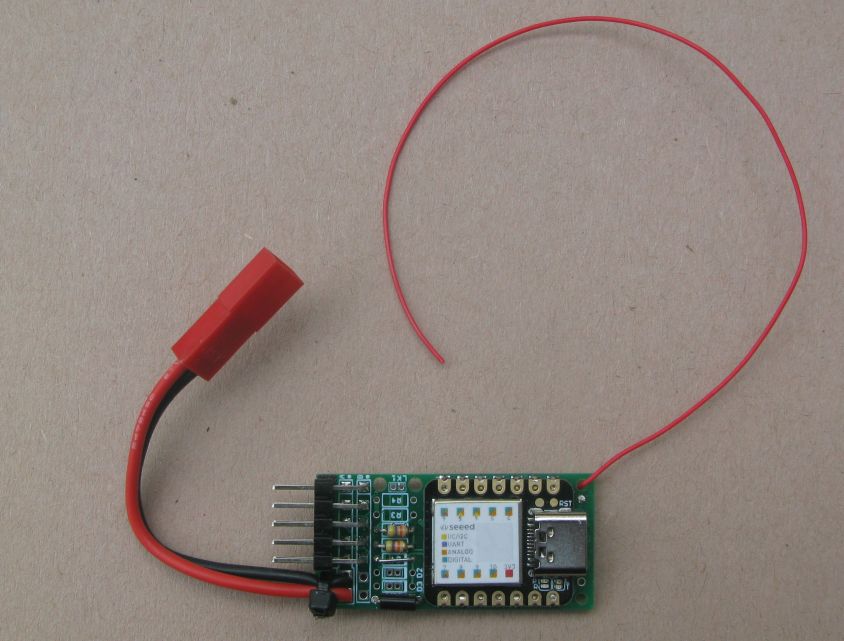
The board described earlier, see below, for the XIAO and LoRa module is for applications where a compact node is important. The board can easily be covered in heat shrink film or wedged in a small project case;
Larger but more versatile
For a lot of applications size is not so much an issue so a board that was easier to build would be good. The board below is easier to build than the compact board above, the XIAO and RFM9X LoRa module do not need to be surface mounted, they can be soldered in place with pin headers.
Although this board is larger; its still only the size of a 3 x AAA battery pack.
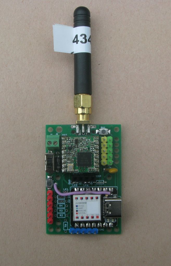
The board can be used as it is above, secured in a case of some sort, with the SMA antenna socket on the outside.
There are, after the pins for the LoRa module are used, 5 IO pins available, which can be used for digital, analogue, I2C or serial UART. There is also a connection for the SPI bus shared with the LoRa module and this allows another SPI device such as an SD Card to be added for logging or saving data.
The yellow pin header is CONA for I2C, the green is CONB for serial UART, red is connector SD for an SD card or other SPI device, and blue is CONC another connector for the serial UART port.
The XIAO is fitted to the board with the pin headers it comes provided with. The RFM9X LoRa module can be surface mounted or soldered in place with 2mm spacing pin headers. The LoRa antenna can be a simple wire, a SMA edge socket or a u.fl socket.
If you can manage a bit of surface mount assembly you can fit two small push buttons, one can be wired to the XIAO reset pin and another can connect to an XIAO IO pin. Both switches can instead be connected to external switches via 2 pin 0.1” header pins.
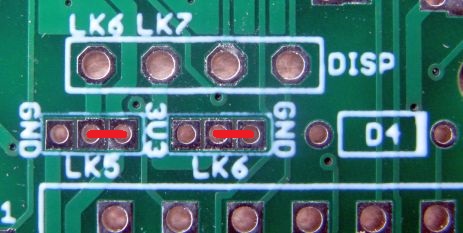
The is an additional 4 pin 0.1” pin header, marked ‘DISP’ just below the LoRa device which allows you to plug in an I2C OLED. The pin layout can be configured via jumpers for the two common types of wiring on an I2C OLED, GND,VCC,SCL,SDA or VCC,GND,SCL,SDA wiring. VCC is 3V3 on the Hand-held XIAO LoRa Transceiver board.
For an OLED that is wired GND,VCC,SCL,SDA fit the GND pin of LK5 to the centre pin of LK5 and the 3V3 pin of LK6 to the centre pin of LK6 like this, links to fit are in red;

For an OLED that is wired VCC,GND,SCL,SDA fit the 3V3 pin of LK5 to the centre pin of LK5 and the GND pin of LK6 to the centre pin of LK6 like this;
The board can be fitted with a 2 pin 0.1” pin header or a screw terminal connector for the battery. You can fit a power switch (SW3), a supply reverse protection diode (D1) and a polyfuse (FS1) for the external supply. Short across these parts with wire links if you don’t want them.
You need to decide how to connect up the DIO pins on the RFM9X for the LoRa examples sketches to work. There are several options for connecting up the DIO pins on the RFM9X. You can connect DIO0,DIO1 and DIO3 up to be read on the same XIAO pin A1 by fitting diodes D2, D3, D4. The LoRa library used for the provided examples only reads DIO0 on the RFM9X, so fit D4 or use a wire link.
If you have an application, such as LoRaWAN, that needs individual access to DIO0, DIO1 and DIO2, do not fit D2 and D3, but fit wire links LK2 and LK3 which are in the D2 and D3 diode positions respectively. You will loose access to the default serial UART port, but DIO1 will be on pin A6 and DIO2 will be on pin A7.
You can connect quite few different types of hardware to this small board;
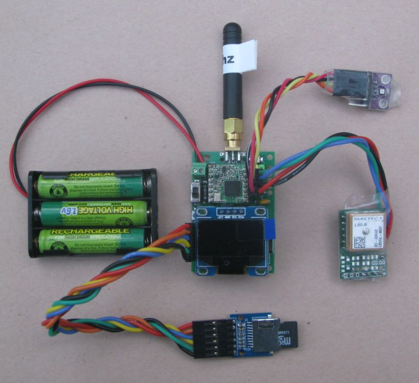
There is a LoRa module, an OLED plugged into the board, a MicroSD card, a GPS and a BME280 sensor. Standard Arduino libraries were used in the example programs.
Example programs
All of the example programs described for the smaller Board for XIAO LoRa described in part 3 can be used on this board, the pin use is the same. So the examples in this repository can be used;
Whilst the board was initially designed for the XIAO SAMD21, you can fit the XIAO RP2040 and you will find some programs for the RP2040 version in the boards repository.
Micro SD card
The XIAO can read and write to a MicroSD card, the pin outs on the SD card match those for one of the low cost MicroSD card holders. See the picture bellow.
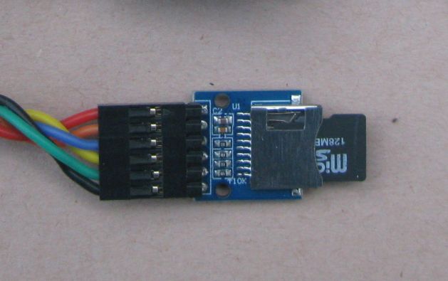
Note that the MicroSD Card used is the type designed for direct use on 3.3V logic, other types designed for general Arduino and 5V logic connections probably will not work. A0 is used for the SD select. To test the SD card load up program 19_SD_Card_Test which will constantly append a number and “Hello World!” to a file and then print out the contents of the file to the serial monitor. If this works then the MicroSD card can be written to and read from.
LoRa packet logger
A useful application for the XIAO is to use it to receive and record to the MicroSD card all the packets it receives. The packet contents are written to a log file in HEX format, together with a time and reception information. Summary details of the packets are sent to a connected I2C display as well. This is program 20_LoRa_SD_Packet_Logger
The boards
The board files in Eagle PCB format can be found in this device repository;
The device repository has example programs, build instructions and layout diagrams also.
LoRa settings for range.
LoRa can use a variety of settings which affect the distance or range at which they can be picked up. The example programs discussed here use Spreading factor 7, bandwidth 125000hz and coding rate 4:5. The GPS tracker packet length is 31 bytes and that would have an air time of 70ms. If you change the LoRa settings to Spreading factor 12, bandwidth 62500hz and coding rate 4:5 the air time increases to 3200mS. This is a long (in time) packet and the distance or range it would be received at increases by about a factor of 8.
Also be aware that while packets that take a long time to send sound OK because they go a lot further, be aware of legal duty cycle limits for your part of the world. In the 434Mhz band you often can only transmit 10% of the time. In these circumstances you could only send one of those long distance 3200mS packets once every 32 seconds.
Conclusions.
The Seeeduino XIAO SAMD21 is a good board, I do like it, small, fast, plenty of memory, on board real time clock (RTC), compatible with a lot of Arduino stuff and easy to build with.
Just my opinion
However, the permanent fitting of the power LED, which I removed to get a very low sleep current, could be corrected. With the power LED in place the ‘sleep’ current is around 1.5mA plus, which is far too high for a lot of battery applications where you want long battery life. With the power LED removed the XIAO has a very commendable sleep current, 20uA in switch\pin wakeup and 10uA in RTC wakeup. Maybe the small size of the XIAO makes it difficult to have a user option for the power LED, but it might be an idea to sell a version without the power LED.
The shortage of IO pins does limit the applications somewhat, particularly with the LoRa device needing so many pins, up to 9 for some applications. The processor used by the XIAO is apparently the SAMD21G18 and although I have not looked under the screening can the processor is listed as a 48pin device, so there may be heaps of un-used IO pins. Increase the length of the board just a little, 1mm maybe, and there might be room for another 6 IO pins on the end. That would be a very useful board indeed.
XIAO ESP32C3 and XIAO RP2040
The pinout of the SAMD21 XIAO is the same as the ESP32C3 and RP2040 versions so the two board described in these articles should work with these versions too. Will report back when I have tested them.
Example programs repository
The example programs for the board can be found here Handheld XIAO LoRa Tranceiver.