Easy Build ESP32 Board
For some time I have wanted an easy to put together portable and hand held LoRa receiver that would have enough resources to be used for receiving files and images over LoRa. The board needed an SD card and a small display.
To make the board multi purpose there should be connectors for adding external sensors or a GPS. It would be useful for the board to have Bluetooth and WiFi capability.
So in summary the board needed;
- To be easy to put together, avoiding the need for SMT assembly.
- A micro controller with plenty of memory.
- A Mikrobus compatible socket so a wide range of LoRa or Click boards could be used.
- An SD card holder.
- A small OLED display.
- Preferably Bluetooth and WiFi capability.
- Connections for a battery pack.
- Some switches.
- Neopixel LEDs for status indications.
The micro controller I decided on was the NodeMCU ESP32, this has plenty of memory, is ready built and low cost. It comes with 0.1” pins for mounting so fitting it to a board is easy. More I\O pins would have been useful, but after a bit of planning I came up with a workable design, here is a picture of the assembled prototype, I called it the EasyBuildESP32;
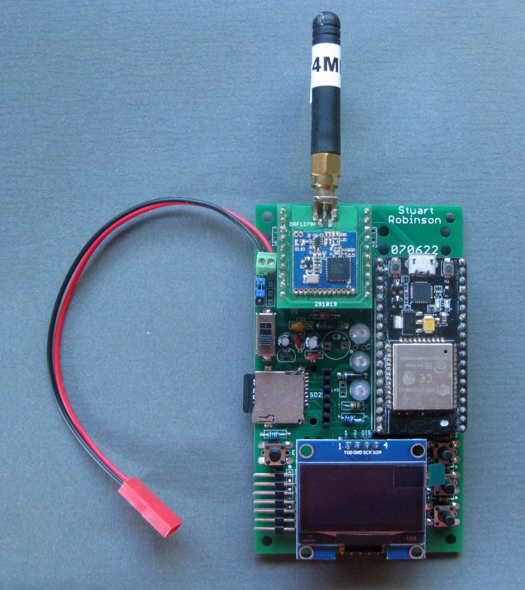
The board has connectors for;
- Mikrobus compatible plug in boards.
- Battery pack.
- I2C external sensors.
- I2C MPR121 3X4 Touch Keypad.
- GPS.
- USB to Serial adapter for serial file uploads to a PC.
I do sell breadboard friendly boards for LoRa devices that can plug into the Mikrobus compatible socket on the EasyBuildESP32 and those for RFM9x and DRF127x UHF devices can be assembled with header pins rather than SMT soldering. You can find the Eagle files for these boards here;
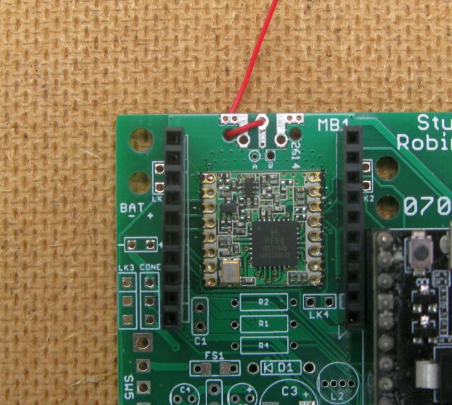
Direct fit of RFM9x or SX1280 LoRa devices.
This first off design of the EasyBuildESP32 has the SMT pads to accept an RFM9x LoRa device direct on the front side and a NiceRF SX1280 (2.4Ghz) LoRa device on the rear. There are connections for an edge SMA antenna socket or a simple wire antenna.
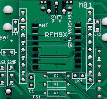
Mikrobus compatible socket
There are holes provide on the NodeMCU board to allow the fitting of an extended Mikrobus socket. A standard Mikrobus socket has two rows of 8 pins on a 0.1” matrix. The bottom two sets of 8 pins in the picture below of the Mikrobus compatible socket on the EasyBuildESP32 board are for a standard Mikrobus plug in board. Some of the LoRa boards I have designed need extra pins for the LoRa devices DIOX connections so two extra pins were added to the top on each side while keeping the overall size of the Mikrobus PCB the same.
Mikroelectronika produce a wide range of Click boards, see here;
The Click boards using 3.3V logic should be compatible with the EasyBuildESP32 board, fit the click board in the bottom 8 pins of the boards Mikrobus socket, the bottom of the socket is marked with a triangle in white on the PCB.
For ease of use, I normally fit two 10 pin 0.1” sockets for the Mikrobus boards, its then easy to swap between different modules. You can however omit the sockets and solder the Mikrobus boards in direct which does make them very low profile on the PCB.
microSD card holders
The microSD card is used on the EasyBuildESP32 in MMC (Multi Media Card) mode. This uses a separate interface on the ESP32 that is dedicated to driving a microSD card in MMC mode. The SD card card could have been driven in SPI mode and then it would share pins with the LoRa device which also runs in SPI mode. However whilst sharing the SPI bus between SD cards and LoRa devices works reliably on some Arduino cores, such as the Arduino DUE and the cores for ATmega328P and ATmega1284P, its not very reliable on the ESP32, after some time the microSD card stops responding.
Driving the microSD card in MMC mode seems to be a lot more reliable.
OLED display connection.
The I2C (Inter integrated circuit) OLED displays can use different connections for VDD and GND. There are links on the board to allow both wirings of VDD and GND to be used.
Switches
There are 4 sets of push button switches used, SW1 to SW4. There is the option of fitting the type of push button that comes in different button lengths (the SWxB parts), or you can use the small rectangular low profile type (the SWxA parts), your choice. There are 3 user programmable switches and a separate switch on the NodeMCU Enable\Reset pin.
Example programs
A series of example programs are provided which test out the various parts of the board. The programs are;
1_LED_Blink
2_Neopixel_Blink
3_LoRa_Register_Test
4_LoRa_Transmitter
5_LoRa_Receiver
6_MMC_SD_Test
7_SSD1306_SH1106_OLED_Checker
8_I2C_Scanner
9_BME280_Test
10_I2C_FRAM_Memory_Test
11_MPR121_3X4_Keypad_Test
12_VIN_Voltage_Read_Test
13_GPS_Echo
14_GPS_Checker_With_Display
15_Switch_Test
16_LoRa_Packet_Logger_With_Display
17_MMC_SDfile_Transfer_Transmitter
18_MMC_SDfile_Transfer_Receiver
19_ArduCAM_Capture2MMC
20_ArduCAM_Image_Transfer
Application programs
Whilst most of the example programs above are intended to be used for testing the board, some of them are useful applications, these programs are;
16_LoRa_Packet_Logger_With_Display. Displays information on the OLED display on packets received. More information, including the contents of the packet in hexadecimal are sent to the serial monitor and logged to the SD card. Can be useful for testing for LoRa reception.
17_MMC_SDfile_Transfer_Transmitter This program can easily be adapted to transfer files\images of choice from the SD card on one board to the SD card on another remote board. Files are fully error checked and depending on the LoRa settings used the link can be over many kilometres.
18_MMC_SDfile_Transfer_Receiver Matching receiver for 17_MMC_SDfile_Transfer_Transmitter program.
19_ArduCAM_Capture2MMC This example uses an ArduCAM OV2640 to take pictures and save them to the SD card. Note you will need to install the ArduCAM ESP32S UNO core in the Arduino IDE, this core is not compatible with previous ArduCAM libraries, so they will probably need to be deleted.
In this example an RFM95 was fitted direct to the board and the Arducam OV2640 was plugged into the Mikrobus socket.
![]()
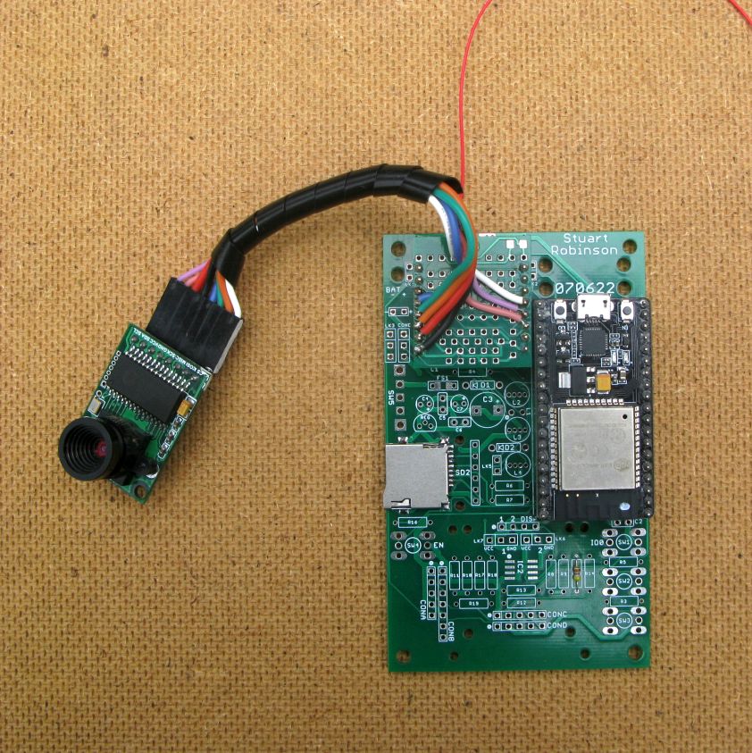
20_ArduCAM_Image_Transfer This is a fully working application. Images taken by the ArduCAM OV2640 are saved to SD card then transferred via LoRa to another remote board running program 18_MMC_SDfile_Transfer_Receiver. Useful for remote monitoring perhaps.
Adding an external power supply
For portable use the board can be powered from a USB power bank plugged into the NodeMCU USB socket. Or you can fit the components that will allow a pack of AA batteries to power the board. This battery pack could be fixed to the back of the PCB.
Gerber files and Support
Its possible that at some time in the future I will sell these PCBs, but for now you can use the Gerber files in the board repository to get your own boards made.
The only condition of use for these Gerber files is that you do not get the boards made and sell them on to others.
Also appreciate that I cannot provide support for using this board for applications other than the programs in the \examples folder. If the examples don’t work for you its most likely you have a build or part error.