Long Range Wireless Adapter for ESP32CAM
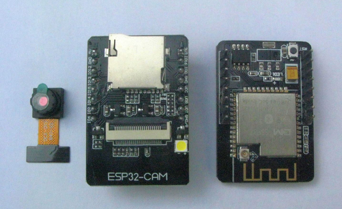
The ESP32CAM is a low cost Micro controller with a camera, micro SD card socket, WiFi and Bluetooth. This article describes a circuit board that can be used to connect a LoRa radio module to the ESP32CAM. The LoRa module will allow the transfer of the images taken by the ESP32CAM over very much longer distances that would be possible with WiFi or Bluetooth.
Is there enough pins for a LoRa device ?
When you look at the IO pins available on the ESP32CAM, assuming the SD card is used in MMC 1bit mode, they are somewhat limited;
| ESP32CAM Pin | SD_MMC Function | Other Function |
|---|---|---|
| UOR | not used | Program upload RX |
| UOT | not used | Program upload TX |
| 2 | DATA0 | not used |
| 4 | DATA1 - not used | White LED |
| 12 | DATA2 - not used | not used |
| 13 | DATA3 - not used | not used |
| 14 | CLK | do not use |
| 15 | CMD | not used |
| 16 | not used | PSRAM Select |
Using a LoRa module with the ESP32CAM is not going to be so easy, these are the pins normally needed to make a SX1278 LoRa LoRa module work; NSS,NRESET,DIO0,SCK,MOSI and MISO. In addition the SX1280 (2.4Ghz) and SX1262 (UHF) LoRa modules need another input pin, RFBUSY.
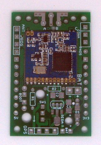
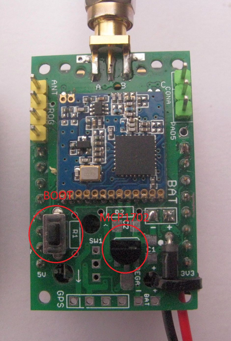
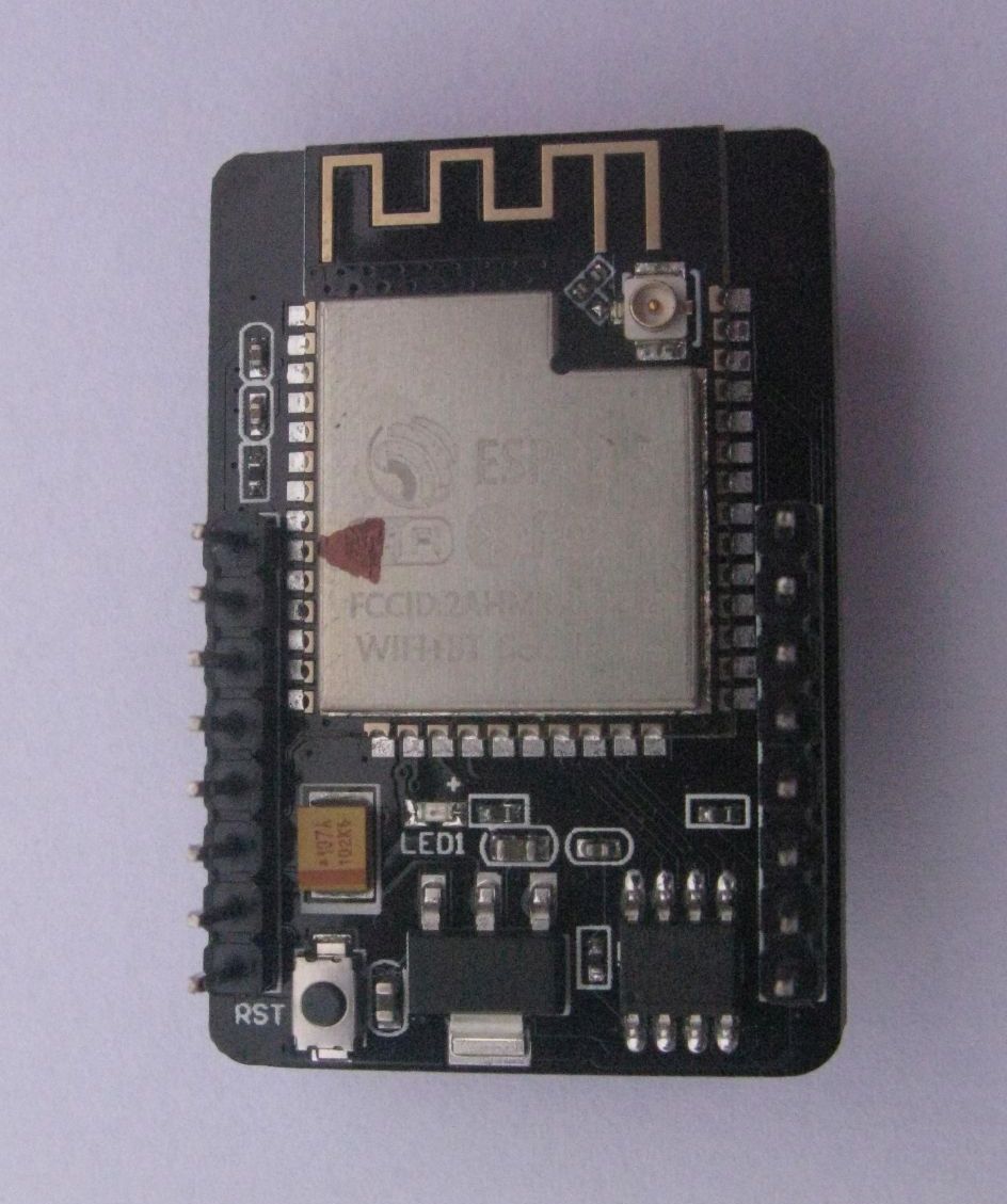
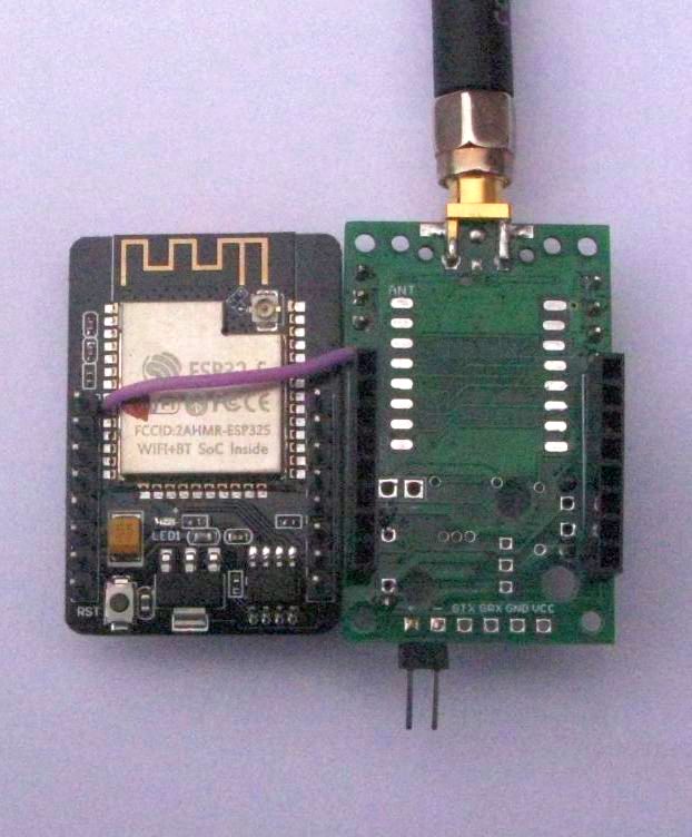
You can, with a suitable library, avoid the need for reading the LoRa modules TXDone and RXDone status pin (DIO0) by reading the devices internal registers. So we need 5 IO pins and from the table above only 4 are available. The solution used is to free up GPIO pin 4 so that the White LED is not used, I removed its switching transistor, see component circled in red in the picture below.
![]()
So the table of connections for LoRa looks like this;
| ESP32CAM Pin | SD_MMC Function | LoRa device function |
|---|---|---|
| UOR | not used | not used |
| UOT | not used | not used |
| 2 | DATA0 | MOSI |
| 4 | DATA1 - not used | SCK |
| 12 | DATA2 - not used | NSS |
| 13 | DATA3 - not used | MISO |
| 14 | CLK | do not use |
| 15 | CMD | NRESET |
| 16 | not used | PSRAM Select |
The above pinout, provided the SD card and LoRa module are used in the right order in software, allows the ESP32CAM to use both the SD card for saving images taken by the camera and the LoRa module for transmitting the pictures.
The Long Range Wireless Adapter board used as an image transmitter needs another Arduino with a matching LoRa module connected to act as the receiver. The received images are saved as a file on an SD card. Another Long Range Wireless Adapter board with an ESP32CAM board can act as the receiver.
In addition to saving the transmitted images to the SD card, there is a version of the receiver program that can transfer the images via the normal program Serial upload port to a folder on a connected PC. I normally use an Arduino DUE for these PC uploads as the DUE has multiple hardware serial ports. I have a shield for the DUE that accepts Mikrobus compatible LoRa modules.
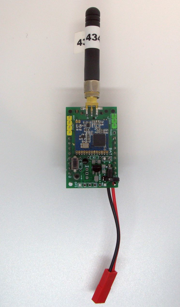
Build Options for Long Range Wireless Adapter with DRF1278F 434Mhz LoRa device
This board, numbered 271121 comes with a Dorji DRF1278F 434Mhz module soldered in place, an SMA antenna socket, a small switch and some pin headers. For a minimal working setup you need to do the following;
First check that your ESP32CAM is fully working and can save pictures to the SD card. There is an excellent tutorial on how to do this here;
https://randomnerdtutorials.com/esp32-cam-take-photo-save-microsd-card
Do not proceed to assemble the Long Range Wireless Adapter until you are really really sure your ESP32CAM is fully working.
1 Solder the 2 x 8 pin header sockets in place. You can for a lower profile assembled unit solder the ESP32CAM pins directly to the PCB, your choice.
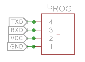
2 Solder the 4 pin 0.1” header in place for the FTDI program upload connector. Its labelled ‘PROG’.
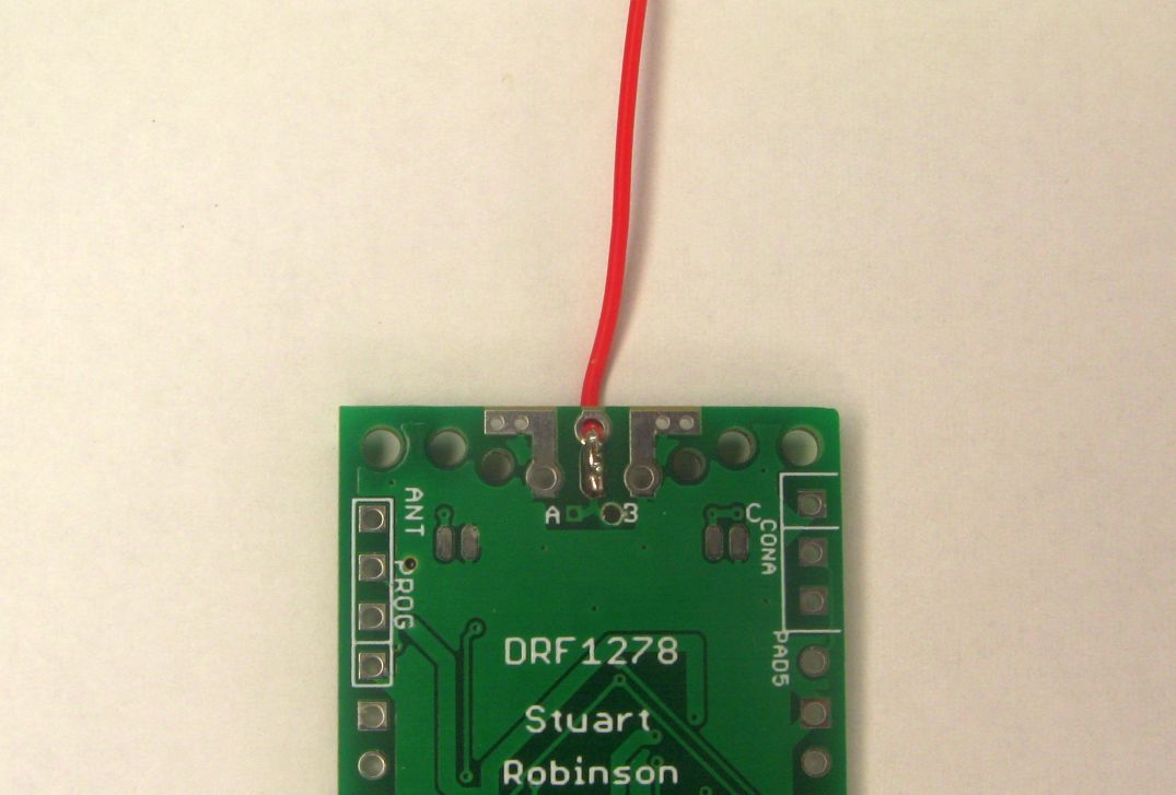
3 Fit the SMA antenna connector and screw in an antenna or use a 17cm length of wire. Do not under any circumstances operate the LoRa module without an antenna connected.
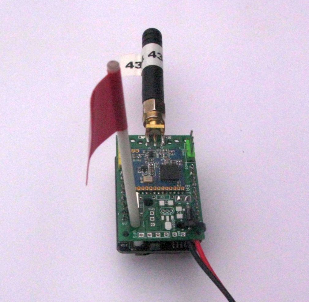
The supplied antenna wire has PTFE insulation, its stiff for its size and low friction so less likely to catch and snap. Its fitted as in the picture below, soldered to the top centre pad of the antenna and fed through the hole on the board edge.
4 Fit the switch that connects DIO0 to GND for programming. Its labelled ‘BOOT’.
5 Connect two wires to the battery connector near the long row of pins on the DRF1278F, its labelled ‘BAT’ and secure the leads with a zip tie or fit an angled pin header at the bottom of the PCB, those pins are labelled ‘BAT’ too.
6 Space is provided on the PCB for a battery reverse protection diode, D1(IN5817) or fuse FS1 (Polyfuse circa 250mA). If you don’t want to fit either the diode or the fuse fit a wire link at the D1\FS1 location. See picture below, where a diode is fitted.
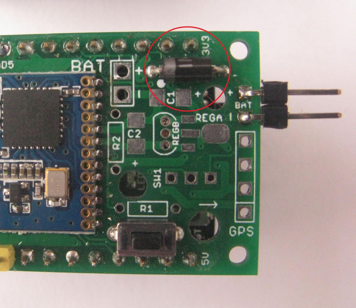
7 Remove the transistor that drives the White LED on the ESP32CAM. This will prevent the White LED flashing every time the LoRa module is used. There is a picture of the location of this transistor towards the top of this article. You can just cut the 3 transistor pins with a sharp blade or lift them with a fine tipped soldering iron.
That’s all that’s needed to get the Long Range Wireless Adapter working. The ESP32CAM and DRF1278F LoRa module will then be powered by the ESP32CAMs AMS1117 3.3V regulator. A battery pack of 4xAA batteries is recommended for this setup.
Programming the ESP32CAM on the Long Range Wireless Adapter
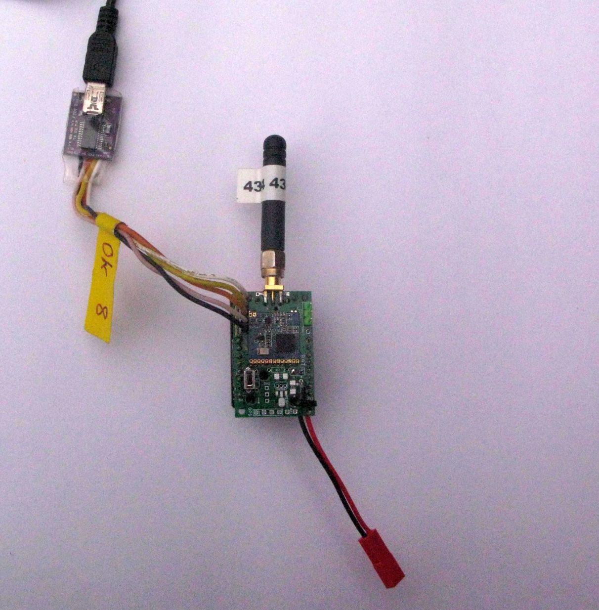
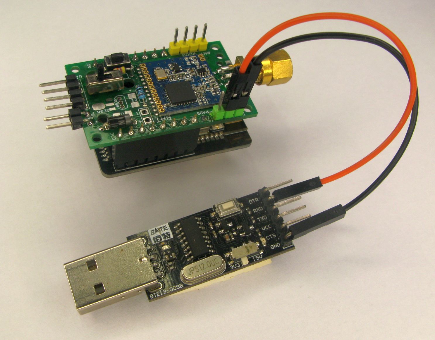
Connect a USB to serial adapter to the 4 pin header at the antenna end of the Long Range Wireless Adapter PCB, the wiring is shown below, pin 1 is the pin furthest away from the antenna end of the PCB. The pinouts are in the same order if you were programming an Arduino Pro Mini;
With the Boot switch on the Long Range Wireless Adapter board held down if you press and release the Reset button on the ESP32CAM you should see the ‘waiting for download’ message in the Arduino IDE (set to 115200 baud).
rst:0x1 (POWERON_RESET),boot:0x3 (DOWNLOAD_BOOT(UART0/UART1/SDIO_REI_REO_V2))
waiting for download
If the ESP32CAM is mounted via the 0.1” header sockets there is room to press the ESP32CAM reset button with your finger or a flat bladed screwdriver. Otherwise there is a hole in the PC to allow a rod to be inserted to press the reset switch.
A bamboo skewer is also about the right diameter for this.
Checking its working
You will have previously tested the ESP32CAM is fully working so all that is now needed is a few simple checks to see if you can upload programs and run programs on the assembled board.
Load program 1_LED_Blink into the Arduino IDE. Press and hold the boot pin switch and then press the reset switch on the ESP32CAM. There is a hole in the Long Range Wireless Adapter board to push a rod through and access the reset switch that way.
With 1_LED_Blink running you should see the ESP32CAM pin 33 red LED flashing, there is a hole in the PCB to allow it to be seen. If the White LED is flashing, that’s not good,** you did not follow the instruction above to disable it. **
Next load up and run program 2_ESP32CAM_DeepSleep_Test. This program should print a message in the Serial monitor saying that the DRF1278F LoRa device was found;
LoRa device found
The program will then flash the red LED and go into a deep sleep for 30 seconds. If the ESP32CAM is battery powered with the original ESP32CAM AMS1117 regulator fitted this current is 1.8mA or so when no SD is fitted and 1.3mA when the optional MCP1702 regulator is fitted. The advantage of the MCP1702 is that at the operating current the drop-out voltage is only about 100mV so operation from a voltage supply of circa 3.4V is possible. The AMS1117 as fitted on the ESP32CAM has a drop-out voltage that could be as high as 1000mV, making low voltage operation problematic. If the supply\battery input voltage is more than 6.5V use an MCP1702 regulator(max input volts 13.2V) otherwise you could use an MCP1700 (max input volts 6.5V)
You now need to load the 3_ESP32CAM_Transmit_Picture program that will transmit the images taken. To receive the images you can use a second Long Range Wireless Adapter and ESP32CAM running program 4_ESP32CAM_Receive_Picture.
As and alternative the SX12XX library does have another program that will receive the transmitted image and save it to SD; 234_SDfile_Transfer_Receiver which typically is run on an Arduino DUE.
Both the transmitter and receiver programs will show the progress of the picture taking and transfer process on the Arduino IDE Serial monitor.
Low power options
If you remove the ESP32CAMs AMS1117 regulator, with a soldering iron or very carefully with a fine pair of wire cutters you can fit the Long Range Wireless Adapter board with a low drop-out voltage regulator which would then allow operation from a single lithium battery or 3 x AA batteries. If your just going to be using the ESP32CAM with LoRa then an MCP1702 regulator will be OK, maximum input voltage 13.2v. If your also going to use the WiFi capability of the ESP32CAM then a HT7833 regulator is recommended, maximum input voltage 8.5v, it has a higher current capability (500mA) than the MCP1702 (250mA). You can fit a TO92 or SOT89 package regulator. If using the HT7833 regulator the fitting C1 and C2 is recommended also.
Other optional components
Resistors R1 and R2 can be fitted and it allows for reading the battery voltage. This might be useful if your also trying to use the Long Range Wireless Adapter as a GPS tracker with the GPS fitted to the 4 pin connector at the bottom of the PCB. There is a program 20_Read_Battery_Voltage_Calibrate that can be used to check the calibration of the battery read. If you have the second serial port working, see the ‘Serial port for monitoring or progress messages’ section below, you can use the program 21_GPS_Echo to copy characters received from the GPS to the second serial port so you can check its working.
SW1 is a small switch that can e fitted which will disconnect the GPS, if fitted, temporarily from the UOR\RXD pin to allow program uploads to be carried out. if you cannot find a switch with the required 2mm pin spacing then a 0.1” pin header and jumper will just fit. For the GPS to operate the two bottom pins of the switch (nearest the GPS connector) need to be connected. To program the ESP32CAM either disconnect the GPS or remove the connection from the bottom two pins.
Picture File Uploads to PC
The image receive program receives the picture (from the remote ESP32CAM) as a series of segments and writes these into a memory array. When the transfer is finished this array is written as a file to the receivers SD card. This normally means that to see the images you need to remove the SD card from the ESP32CAM and read it in a tablet or PC etc. Whilst the SD card is out of the receiving ESP32CAM transfer of images is halted.
To work around this issue it is possible to transfer the contents of the array as an image over the serial program upload port to an attached PC. The protocol used is YModem and its received on the PC with Tera Term, see setup instructions below.
It makes sense to test that you have Tera Term set up correctly on the PC before proceeding to use it to transfer images from the remote ESP32CAM. A test program is provided for this purpose; 5_ESP32CAM_PCFileTransfer_Test, so load this onto the Long Range Wireless Adapter your using as a receiver.
Tera Term - Setup Serial Port
I was using version 4.106 of Tera Term.
After the ESP32CAM is loaded with the 5_ESP32CAM_PCFileTransfer_Test program you need to configure Tera Term to use the correct program upload port for file transfers.
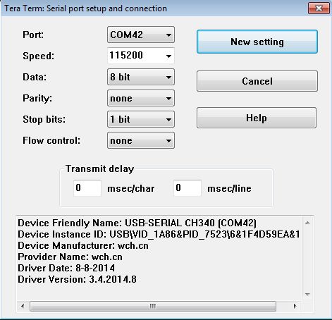
On my PC, Windows8, the USB to serial adapter, that’s used to program the ESP32CAM, turns up on port COM42 so in Tera Term select \Setup\Serial Port… and configure for 115200 baud, see below;
Tera Term - Setup File Transfer directory
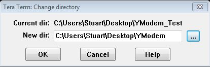
Tera Term needs to know where to save the files transferred. You probably need to change it, as it will default to its own program directory. I created a folder on my desktop called YModem and in Tera Term selected \File\Change Directory and browsed to the YModem directory;
If you want to make the change the default, so you don’t have to set it every time, locate the TERATERM.INI file in the Tera Term program directory and alter this line to point to a folder of your choice;
FileDir=C:\Users\Stuart\Desktop\YModem`
Timeouts on Tera Term
I noticed that if you leave the transfers and YModem uploads running, that after the first image is sent when the next YModem transfer starts there is a delay after the PC picks up the file name of the impending transfer before the actual transfer starts. This delay was around 20 seconds. If this delay is a problem then load the TERATERM.INI file, located in the Tera Term program folder into an text editor and you will find this section;
; YMODEM Timeout value(v1,v2,v3,v4,v5) by seconds
;  v1=NAK mode: Timeout value for first packet
;  v2=CRC mode: Timeout value for first packet
;  v3=Timeout short time
;  v4=Timeout long time
;  v5=Timeout very long time
YmodemTimeouts=10,3,10,20,60
Note the line; YmodemTimeouts=10,3,10,20,60. The value 20, highlighted in bold can be changed to say 1 and the delay mentioned above does not occur.
Tera Term - Start File Transfers
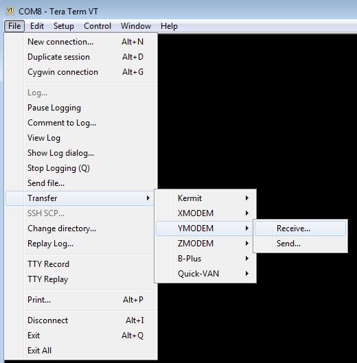
To start Tera Term file transfers running, in Tera Term select, \File\Transfer\YMODEM\Receive..
And that’s it, the transmitting program, 5_ESP32CAM_PCFileTransfer_Test, should now attempt to transfer a test file called TESTFILE1.TXT. The program first allocates an array in PSRAM and then fills the array with 8 lines of ASCII characters 0x20 to 0x7E. This file is then transferred repeatedly using YModem. The destination directory on the PC should fill up with files called ‘TESTFILE1.TXT’ etc. The file should look like this when loaded up in Notepad.
 !"#$%&'()*+,-./0123456789:;<=>?@ABCDEFGHIJKLMNOPQRSTUVWXYZ[\]^_`abcdefghijklmnopqrstuvwxyz{|}~
 !"#$%&'()*+,-./0123456789:;<=>?@ABCDEFGHIJKLMNOPQRSTUVWXYZ[\]^_`abcdefghijklmnopqrstuvwxyz{|}~
 !"#$%&'()*+,-./0123456789:;<=>?@ABCDEFGHIJKLMNOPQRSTUVWXYZ[\]^_`abcdefghijklmnopqrstuvwxyz{|}~
 !"#$%&'()*+,-./0123456789:;<=>?@ABCDEFGHIJKLMNOPQRSTUVWXYZ[\]^_`abcdefghijklmnopqrstuvwxyz{|}~
 !"#$%&'()*+,-./0123456789:;<=>?@ABCDEFGHIJKLMNOPQRSTUVWXYZ[\]^_`abcdefghijklmnopqrstuvwxyz{|}~
 !"#$%&'()*+,-./0123456789:;<=>?@ABCDEFGHIJKLMNOPQRSTUVWXYZ[\]^_`abcdefghijklmnopqrstuvwxyz{|}~
 !"#$%&'()*+,-./0123456789:;<=>?@ABCDEFGHIJKLMNOPQRSTUVWXYZ[\]^_`abcdefghijklmnopqrstuvwxyz{|}~
 !"#$%&'()*+,-./0123456789:;<=>?@ABCDEFGHIJKLMNOPQRSTUVWXYZ[\]^_`abcdefghijklmnopqrstuvwxyz{|}~
 !"#$%&'()*+,-./0123456789:;<=>?@ABCDEFGHIJKLMNOPQRSTUVWXYZ[\]^_`abcdefghijklmnopqrstuvwxyz{|}~
Files should now be transferred into the selected folder on the PC. Note that the Tera Term receiver will recognise that if the the same file name is being transferred and the destination files will be named, Pic1.JPG, Pic11.JPG, Pic12.JPG etc.
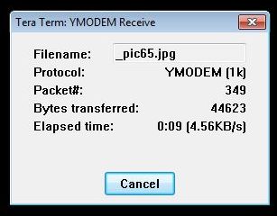
This is the Tera Term window showing the file transfer process;
Serial port for monitoring or progress messages
There is however a slight problem, the Serial port used for the upload of the image to the PC cannot now be used for the normal serial print of monitoring or progress messages to the Serial monitor so a workaround is needed.
The ESP32 does support two hardware serial ports and the pins for RX and TX can be directed to an available IO pin.
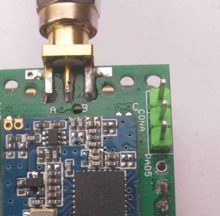
There is a connector on the Long Range Wireless Adapter, its labelled CONA, which can be used to connect an additional serial to USB adapter. There is a pad, labelled PAD5, to enable the centre pin of the 3 pin connector to be connected to a spare IO pin on the ESP32CAM. See picture below;
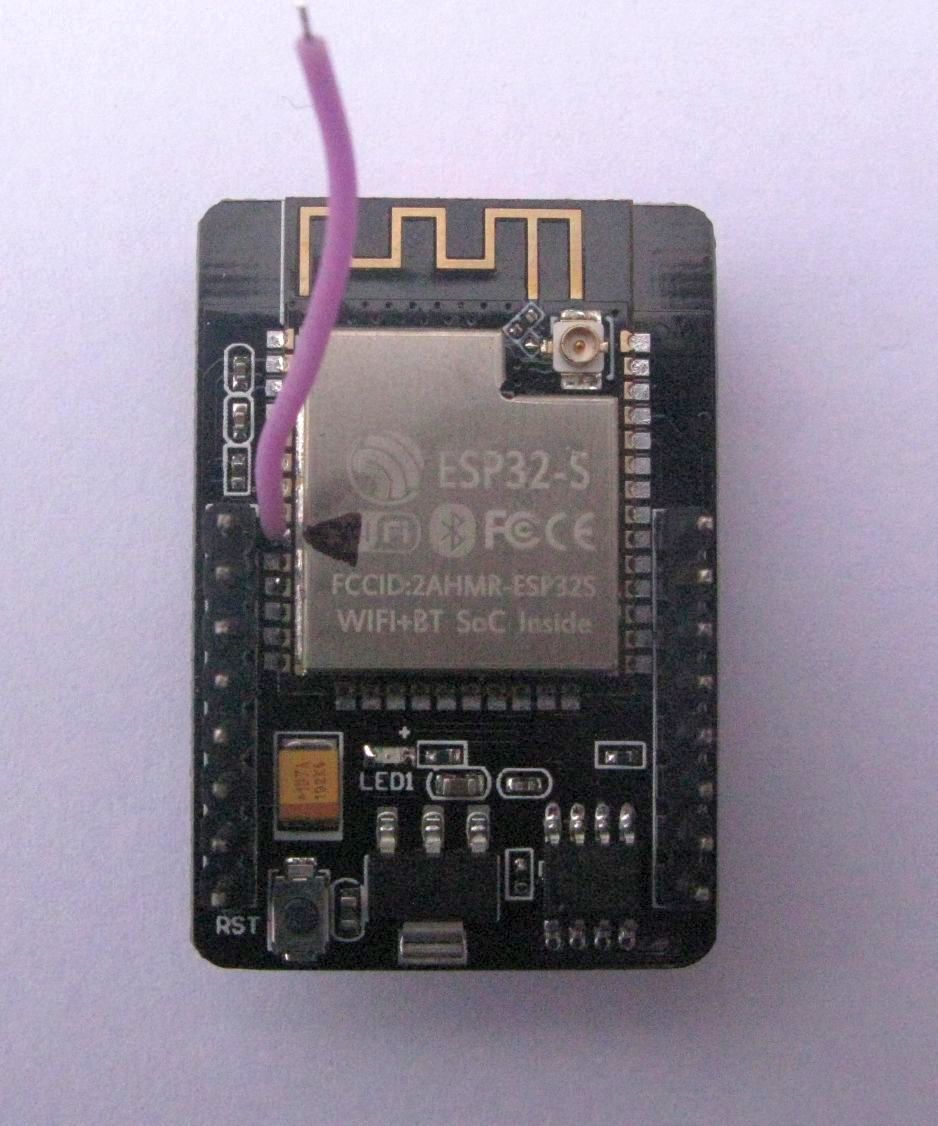
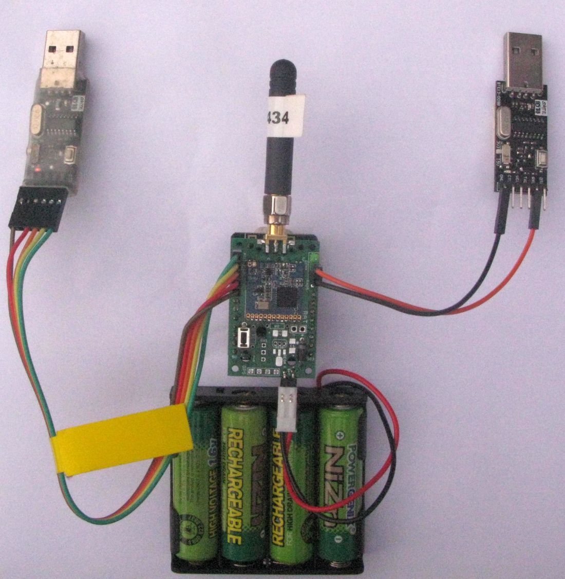
The only truly ‘spare’ pin on the ESP32CAM is GPIO pin 33 which drives the on-board red LED. You need to solder a short wire to pin 33 on the ESP32 module and then connect this wire to PAD5 on the Long Range Wireless Adapter board. The GND pin of CONA is at the end nearest to the DRF1278F, so connect this pin to the GND pin on the second USB to serial adapter and the centre pin of CONA to the RX pin on the USB to serial adapter. The pictures below show where the pin 33 wire is connected on the ESP32 module and where it connects to on the underside of the Long Range Wireless Adapter board.
Below is a picture of the connections for the GPIO pin 33 Serial port;
If you load up program 6_ESP32CAM_Receive_Picture_PCTransfer that is setup to use the primary Serial port for the YModem transfer and Serial2 for the monitor\debug messages, see picture below, primary program upload connection to PC on the left, monitor\debug messages serial connection on the right.
If you can live without seeing the monitor\debug messages then there is no need for the pin 33 modification described above or the second USB to serial converter, the YModem transfer progress to the PC will work without them. The red LED on the ESP32CAM will flash when there is a transfer to the PC in progress.
The Serial2 monitor output (if you can see it) should display this for every completed transfer;
YModem file transfer starting
Waiting for receiver ping ...
done
Ymodem Sending TestFile.txt
873 bytes
........done
YModem transfer OK
Program files and details
The Arduino programs mentioned in this article and details of the board can be found in here Board Details.
The board is no longer available for purchase, but Gerbers of the PCB are available at the link above.
Please note:
I am not, very definitely not, in any way whatsoever an ‘expert’ on the ESP32CAM itself so will leave the task of refining the settings for taking pictures with and support of the ESP32CAM to others.