Serial Bridge
For some time I have thought it would be useful to have a Wireless Serial bridge so you could monitor the Serial output of a remote Arduino or other Serial based device or sensor.
Often when working on an Arduino sketch or application there is useful information output to the Serial monitor. If the Arduino you want to monitor is remote from your workbench then you either need to use a long Serial cable (not always practical) or have something like an Openlog on the Arduinos Serial port, but then you only see what has happened after the event, a real time view would be better.
There are some LoRa modules that are UART\Microcontroller front ended that can in effect be used in this way, but they transmit blindly so the receiver can miss packets and thus the Serial output can be corrupted. Its important to remember that transmission and reception of RF data will not be 100% reliable.
A 2.4Ghz SX1280 LoRa device ought to be fast enough to read data from the a Serial port and send the output on a send and acknowledge basis for reliability. The ‘reliable’ packet options in the SX12XX-LoRa library should provide a good degree of immunity from missed packets, possibly caused by nearby LoRa transmitters or other interference.
The process behind the bridge is basically simple; on the transmitter, check if there are characters in the Serial buffer and if there are copy them into a message array. When there is a time gap in the incoming Serial characters (i.e. a defined time-out) or the message buffer is full, send the message array via LoRa and keep sending it until there is an acknowledgement from the remote receiver.
The receiver is there listening for packets to arrive and when they do it prints the message to the receivers Serial port. The receiver then sends an acknowledgement that the transmitter is waiting for.
Its possible that the transmitter will not receive the acknowledge from the receiver so the transmitter will send the same message again. This means the receiver gets the same message twice and we only want to send the message to the receivers Serial port once.
So some mechanism for recognising duplicate messages is needed. This is allowed for by having the transmitter set the first two bytes of the message to a message number. The receiver can then use the message number included in the packet to tell if it has previously received the message and then just resend the acknowledgement without re-printing or re-using the message. Thus with the library reliable packet functions adding the networkID and payload CRC at the end of the packet for security and checking, a transmitted packet looks like this;
<MessageID><MessagePayload><NetworkID><PayloadCRC>
The 16 bit NetworkID can be used to direct packets to a particular receiver and also ensure that only packets from a known source are accepted. The PayloadCRC is a check that the packet contents are valid.
There are some other situations that the Serial bridge may need to deal with. First it would be useful for the bridge transmitter to send control packets to the receiver, such as message indicating it has powered up or re-started. To allow for this the transmitter starts sending its received Serial input from message number 257 (0x0101). Message numbers 0 to 255 (0x0000 to 0x00FF) are assumed to be control messages of some sort.
Another situation to deal with is if the transmitter has been restarted and thus it starts sending Serial payloads from message 257 again. The receiver needs in these circumstances to reset the last received message number so that at the next message it is now expecting message 258.
So in principle these are the logic steps the receiver follows;
Receive a packet, if the Packet length is 0, there has been an error, ignore the packet.
If the Received Message number is greater than the last received message, process the message.
If the Received Message number is 257, reset the last message number and process the message.
If the Received Message number is less than 256, process the control message.
Set Last received message number to the current received message number.
Repeat.
With the basics of the above coded up, I attached the Serial bridge transmitter, based on an Arduino Pro Mini to another Pro Mini running a GPS tracker program, 23_GPS_Tracker_Transmitter.ino from the SX12XX-LoRa library. Those devices were placed on a table outside in my garden;
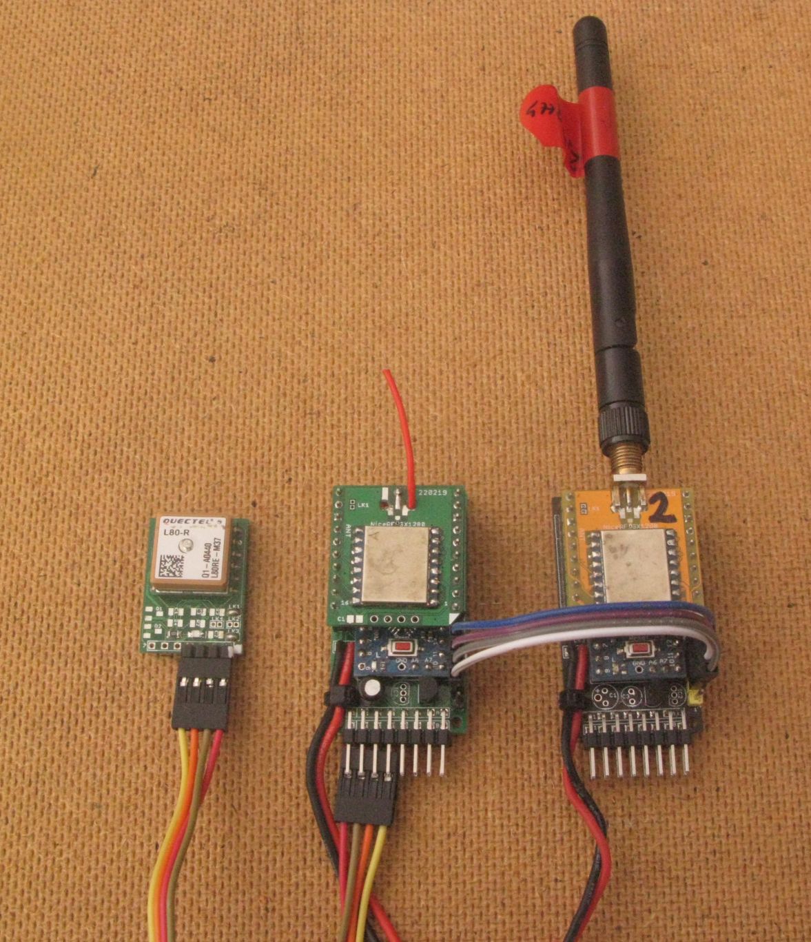
The GPS tracker is the Arduino in the middle, the transmitter that will monitor and send the tracker Serial output to the remote receiver is on the right.
The output of the bridge was monitored on an Arduino DUE running on the bench in my workshop (posh name for a Shed).
The output of the GPS tracker at start-up received over the Serial bridge was as expected;
23_GPS_Tracker_Transmitter Starting
LoRa Device found

SX1280,PACKET_TYPE_LORA,2444999936hz,SF12,BW203125,CR4:5 SX1280,PACKET_TYPE_LORA,Preamble_12,Explicit,PayloadL_255,CRC_ON,IQ_NORMAL,LNAgain_HighSensitivity
Supply 5188mV
Send Cmd P - Done
Startup GPS check
$GPGSA,A,1,,,,,,,,,,,,,,,*1E
$GPGSV,1,1,00*79
$GPRMC,235945.262,V,,,,,0.00,0.00,050180,,,N*4B
$GPVTG,0.00,T,,M,0.00,N,0.00,K,N*32
$GPGGA,235946.262,,,,,0,0,,,M,,M,,*41
$GPGLL,,,,,235946.262,V,N*73
$GPGSA,A,1,,,,,,,,,,,,,,,*1E
$GPGSV,1,1,01,05,,,31*7F
$GPRMC,235946.262,V,,,,,0.00,0.00,050180,,,N*48
$GPVTG,0.00,T,,M,0.00,N,0.00,K,N*32
$GPGGA,235947.261,,,,,0,0,,,M,,M,,*43
$GPGLL,,,,,23594

Wait for first GPS fix
Wait GPS Fix 1800s
So the basics of the Serial bridge were working.
To test the Serial Bridge code further and to replicate the situation of a simple Serial sensor outputting a lot of data a GPS was connected directly to the Serial (programming port) of the Serial bridge transmitter so that the Serial bridge receiver would get and could show or use all the Serial output of the remote GPS;
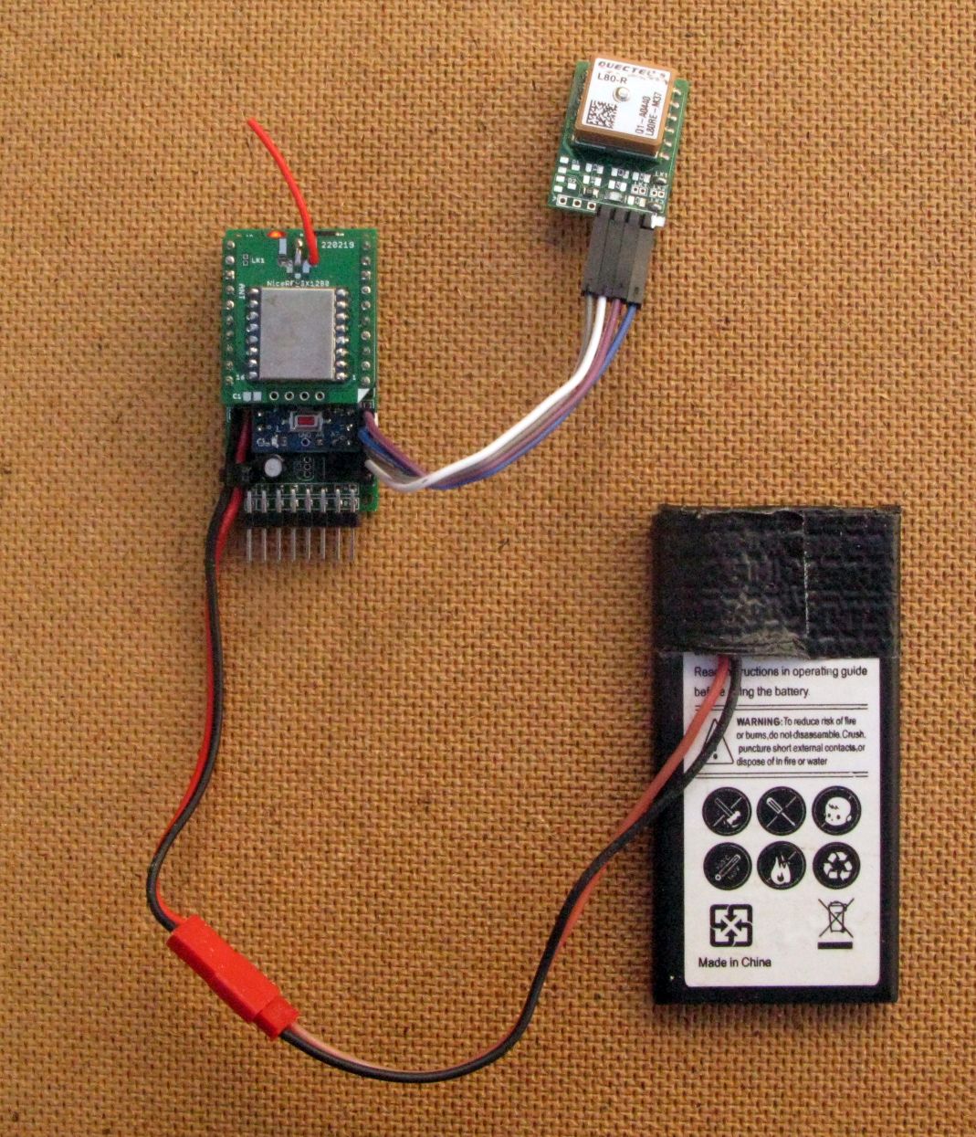
At power up of the GPS and Serial bridge transmitter outside the receiver shows this output;
Ready
$GPVTG,0.00,T,,M,0.00,N,0.00,K,N*32
$GPGGA,235953.262,,,,,0,0,,,M,,M,,*45
$GPGLL,,,,,235953.262,V,N*77
$GPGSA,A,1,,,,,,,,,,,,,,,*1E
$GPGSV,1,1,02,25,,,41,32,,,34*7F
$GPRMC,235953.262,V,,,,,0.00,0.00,050180,,,N*4C
$GPVTG,0.00,T,,M,0.00,N,0.00,K,N*32
$GPGGA,235954.262,,,,,0,0,,,M,,M,,*42
$GPGLL,,,,,235954.262,V,N*70
$GPGSA,A,1,,,,,,,,,,,,,,,*1E
$GPGSV,1,1,03,25,,,41,32,,,33,31,,,35*7D
$GPRMC,235954.262,V,,,,,0.00,0.00,050180,,,N*4B
$GPVTG,0.00,T,,M,0.00,N,0.00,K,N*32
$GPGGA,235955.262,,,,,0,0,,,M,,M,,*43
$GPGLL,,,,,235955.262,V,N*71
$GPGSA,A,1,,,,,,,,,,,,,,,*1E
$GPGSV,1,1,03,25,,,40,32,,,33,31,,,37*7E
$GPRMC,235955.262,V,,,,,0.00,0.00,050180,,,N*4A
$GPVTG,0.00,T,,M,0.00,N,0.00,K,N*32
$GPGGA,235956.262,,,,,0,0,,,M,,M,,*40
$GPGLL,,,,,235956.262,V,N*72
$GPGSA,A,1,,,,,,,,,,,,,,,*1E
$GPGSV,1,1,03,25,,,39,32,,,33,31,,,37*70
$GPRMC,235956.262,V,,,,,0.00,0.00,050180,,,N*49
$GPVTG,0.00,T,,M,0.00,N,0.00,K,N*32
$GPGGA,235957.262,,,,,0,0,,,M,,M,,*41
$GPGLL,,,,,235957.262,V,N*73
$GPGSA,A,1,,,,,,,,,,,,,,,*1E
$GPGSV,1,1,03,25,,,40,32,,,33,31,,,37*7E
$GPRMC,235957.262,V,,,,,0.00,0.00,050180,,,N*48
$GPVTG,0.00,T,,M,0.00,N,0.00,K,N*32
$GPGGA,235958.262,,,,,0,0,,,M,,M,,*4E
$GPGLL,,,,,235958.262,V,N*7C
$GPGSA,A,1,,,,,,,,,,,,,,,*1E
$GPGSV,1,1,03,25,,,40,32,,,33,31,,,37*7E
$GPRMC,235958.262,V,,,,,0.00,0.00,050180,,,N*47
$GPVTG,0.00,T,,M,0.00,N,0.00,K,N*32
$GPGGA,235959.262,,,,,0,0,,,M,,M,,*4F
$GPGLL,,,,,235959.262,V,N*7D
$GPGSA,A,1,,,,,,,,,,,,,,,*1E
$GPGSV,1,1,03,25,,,40,32,,,33,31,,,37*7E
$GPRMC,235959.262,V,,,,,0.00,0.00,050180,,,N*46
$GPVTG,0.00,T,,M,0.00,N,0.00,K,N*32
$GPGGA,000000.262,,,,,0,0,,,M,,M,,*4E
$GPGLL,,,,,000000.262,V,N*7C
$GPGSA,A,1,,,,,,,,,,,,,,,*1E
$GPGSV,1,1,03,25,,,40,32,,,33,31,,,37*7E
$GPRMC,000000.262,V,,,,,0.00,0.00,060180,,,N*44
$GPVTG,0.00,T,,M,0.00,N,0.00,K,N*32
$GPGGA,000000.478,,,,,0,0,,,M,,M,,*43
$GPGLL,,,,,000000.478,V,N*71
$GPGSA,A,1,,,,,,0,0.00,060180,,,N*49
$GPVTG,0.00,T,,M,0.00,N,0.00,K,N*32
$GPGGA,000001.478,,,,,0,0,,,M,,M,,*42
$GPGLL,,,,,000001.478,V,N*70
$GPGSA,A,1,,,,,,,,,,,,,,,*1E
$GPGSV,1,1,03,25,,,40,32,,,33,31,,,37*7E
$GPRMC,000001.478,V,,,,,0.00,0.00,060180,,,N*48
$GPVTG,0.00,T,,M,0.00,N,0.00,K,N*32
$GPGGA,175851.140,,,,,0,0,,,M,,M,,*42
$GPGLL,,,,,175851.140,V,N*70
$GPGSA,A,1,,,,,,,,,,,,,,,*1E
$GPGSV,1,1,03,25,,,40,32,,,33,31,,,37*7E
$GPRMC,175851.140,V,,,,,0.00,0.00,070180,,,N*49
$GPVTG,0.00,T,,M,0.00,N,0.00,K,N*32
$GPGGA,175852.140,,,,,0,0,,,M,,M,,*41
$GPGLL,,,,,175852.140,V,N*73
You can see that the GPS gets the current GPS time fairly quickly.
The transmitter, in the case above, was an Arduino Pro Mini 3.3V so running at 8Mhz only and it seemed able to keep up with reading characters from the GPS and transmitting the Serial stream over a series of LoRa packets.
Now you could go through all the NMEA sentences seen at the receivers Serial monitor output and check them manually for valid checksums but there is an easier way.
To check that the received Serial data via LoRa from the remote GPS is valid, instead of printing to the receivers Serial monitor, you can feed the characters into the TinyGPSplus library and have the library report the GPS fix status as well as the number of NMEA sentences (received from the GPS over the Serial bridge) that had a valid checksum and the number of NMEA sentences that failed the checksum, this was the output;
NMEA 5271 0
NMEA 5276 0
GPS Fix > Lat,74.634148,Lon,14.562181,Alt,51.3m,Sats,8
NMEA 5279 0
NMEA 5284 0
GPS Fix > Lat,74.634148,Lon,14.562181,Alt,51.3m,Sats,8
NMEA 5287 0
NMEA 5292 0
GPS Fix > Lat,74.634148,Lon,14.562183,Alt,51.3m,Sats,8
NMEA 5295 0
NMEA 5300 0
The NMEA 5271 0 at the start of the log above indicates the Serial bridge receiver detected 5271 NMEA sentences with a valid checksum and no checksum fails.
Programs 105_LoRa_Serial_Bridge_Transmitter, 106_LoRa_Serial_Bridge_Receiver and 107_LoRa_Serial_Bridge_GPS_Receiver can be found here;
SX12XX-LoRa\examples\SX128x_examples\SerialBridge
Stuart Robinson
December 2021