StuartCAM - ESP32CAM Getting the SD card to Work
The ESP32CAM has an SD card but unfortunately it uses the same pins that the SPI interface needs for the LoRa device. So there are going to be conflicts and whilst I initially had it working, with the image transfer, after a few deep sleeps and wake ups the SD card would stop initialising. It had to be removed or otherwise powered down and put back in to recover.
Clearly it would be helpful if the images taken were also saved on the ESP32CAM SD card.
UHF SX127X LoRa device
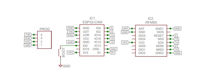
This is the original circuit I had used for StuartCAM with SX127X;
When we look at the functions of the pins that the ESP32 uses on the SD_MMC interface to access the SD we see;
| ESP32CAM Pin | SD_MMC Function | SPI LoRa Function |
|---|---|---|
| 2 | DATA0 | MOSI |
| 4 | DATA1 (not used) | NRESET |
| 12 | DATA2 (not used) | not used |
| 13 | DATA3 (not used) | NSS |
| 14 | CLK | SCK |
| 15 | CMD | MISO |
| 16 | not used | not used |
The SD_MMC is used in 1 pin mode so that data or commands are clocked via DATA0 only, DATA1,DATA2,DATA3 are not used. To set the SD_MMC to this 1 bit mode you initialise it with this function;
SD_MMC.begin(“/sdcard”, true));
You can see from the table above that the clock pin for the SD_MMC is the same as the SPI SCK pin so when the SPI for the LoRa device gets used the SD card may well receive spurious commands that confuse it; so perhaps that’s why it locks up after a few cycles.
GPIO14 SD-MMC CLK
Could we keep the SD_MMC CLK pin on GPIO14 clear of activity so the SD card behaves more reliably ?
GPIO4 on the ESP32CAM is used by the white LED, so to free up this pin for the LoRa device I removed its switching transistor, see picture below.
![]()
We can now assign GPIO4 for the LoRa device SPI SCK and the SD_MMC CLK pin (on GPIO14) is now clear of interference. I made this change on my stripboard setup and loaded the code up.
Success !
The picture transfer code was run for some 350 wake ups and saved the image to SD card every time and then successfully transfered the image with LoRa as before. Progress.
GPIO12 and GPIO16
There are now two unused pins, GPIO12 and GPIO16. GPIO16 is the PSRAM select for the ESP32CAM and whilst we could use it for the LoRa device picture size would then be limited to 800x600, larger images require the use of the PSRAM.
GPIO12 can be used but we need to be sure to leave it floating during programming or reset as its used internally by the ESP32 to sense the correct voltage for the Flash. An external pull-up of 47K or higher seems to be OK. So we could use it for the LoRa devices NSS as long as we don’t put a low value pull up resistor on this pin. I did try 10K, which would be a normal value for an SPI CS pull-up resistor but it produces an ESP32 Flash error on start-up, so for now I removed the pull-up.
MISO was moved from GPIO15 (SD_MMC CMD) to GPIO13 which is SD_MMC DATA3 which should be unused.
The pinouts are now, with NRESET not connected;
NSS 12, SCK 4, MISO 13, MOSI 2
LoRa device NRESET
Can we get NRESET working, as that would guard against potential lock-ups of the LoRa device ?
When the ESP32 wakes up at each picture taking the LoRa device is set-up and there should ideally be a short pulse on NRESET before the actual set up. This single pulse on the SD_MMC CLK pin (GPIO14) might not be an issue so I tried it.
More Success !
The picture taking ran for 125 pictures with no SD card lock-ups. Note that we are now not using GPIO15, in part this is deliberate since looking to the future the SX128X and SX126X devices need an input pin to read RFBUSY on those devices.
So if we put the LoRa device NSS on GPIO12 we can leave pin 14 (which is the SD_MMC CLK) alone.
GPIO15 and NRESET
In the specific case of the SX127X we can try and use GPIO15 for NRESET rather than GPIO14 as this would then leave the SD_MMC CLK free of all potential clocks. GPIO15 is the SD_MMC CMD pin and I was hoping the odd clock pulse on here would have no effect if the main SD_MMC CLK pin was not running So that’s what I tried tried next and;
Even More Success !
All the required pins on the LoRa device being driven and the SD card seems to be happy too.
Here is the revised pin-out;
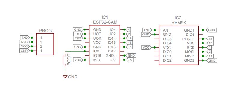
And the allocated pins are;
| ESP32CAM Pin | SPI LoRa Function |
|---|---|
| 2 | MOSI |
| 4 | SCK |
| 12 | NSS |
| 13 | MISO |
| 14 | not used |
| 15 | NRESET |
| 16 | not used |
2.4Ghz SX128X LoRa device
So what happens when this new revised pin-out is tried on the SX128X ? The plan here would be to put NRESET on GPIO14 and RFBUSY on GPIO15. Although GPIO14 is the SD_MMC CLK pin the single pulse on NRESET at start-up did not appear to cause problems when tested with the SX1278 set-up described above.
So I converted the SX127X sketch across to SX128X. With StuartCAM running in FLRC mode in my workshop, an 800x600 image was being transferred across to the receiver in around 670mS. Thats a packet around once every 1.7mS. Gosh thats quick.
I left the transfer program running overnight and by morning around 6000 images had been taken and transferred.
All images were received and stored OK on SD, the receiver was an Arduino DUE. However on the transmitter there was a corrupt image at number 2604. Then there were saved images up to 2623, which were also unreadable, and then there were no more images saved. The serial monitor log did not show any SD errors however, so the ESP32CAM thought the SD card was OK.
I re-formatted the SD cards and swapped them around between TX and RX. This time it was the receiver that had corrupt images after 2052 were saved, the 6,500 images on the transmitter SD were OK. So the failure was caused by the SD card, not a problem with NRESET on the transmitter.
The workaround for the SX128X if NRESET on the SD_MMC CLK pin caused problems was to put a PCA9536 I2C IO expander on the program upload pins and use that device at start-up to reset the LoRa device, but it this workaround does not seem to be be necessary.
Extra Information
I was reading this ESP32CAM tutorial;
https://randomnerdtutorials.com/esp32-cam-ai-thinker-pinout/
And found this comment;
“In order to free pin12 and pin13 (provided you wouldn’t need them for a very demanding SD card usage) you can modify ESP32-CAM fuses like this: (from Terminal window) $ espefuse.py –baud 115200 –port your_USB_port_name set_flash_voltage 3.3V and then include in your Arduino code: SD_MMC.begin(“/sd”, true);”
So that might be worth a try one day.