Large Data Transfers with LoRa - Part2
Keeping Track of the Segments
One consideration for a large data transfer is how does the transmitter know that all the segments have been sent and correctly received when there could be 1000+ segments ? Some reception fails at the receiver seem inevitable due to interference or weak signals.
It would be possible for the receiver to keep track of all the segment numbers it had received, say 0 to 999, then at the ‘end’ of the transfer attempt send back to the transmitter a list of missing segments. These missing segments are then re-transmitted with this process continuing until all the segments have been received. Such a process is a possibility but I was initially concerned about the number of random seeks to different file locations on the SD card and the affect that might have on throughput.
I decided to first implement a simple streaming of the segments; send a segment, wait a time for an acknowledge and then send the next segment. The transmitter would keep transmitting a segment until it had a valid acknowledgement back from the receiver. The receiver would keep track of what segment it had last received and would only add data to the SD file when a new segment had arrived. If the same segment was received twice, which could happen if the transmitter misses the acknowledge, the receiver would again send an acknowledge but with no write to SD, thus maintaining the write position for the SD.
Another consideration for the code was that it should be capable of operating reliably at high speed for short distance applications. The 2.4Ghz SX128X can send LoRa packets at higher data rate than a SX127X so the basic code so far for the SX127X was ported with a few changes to work on the SX128X part of the library so the higher speed performance could be checked. An advantage of 2.4Ghz operation is that you can transmit at 100% duty cycle so you could send files or images continuously.
Testing hardware - Arduino DUE Shield
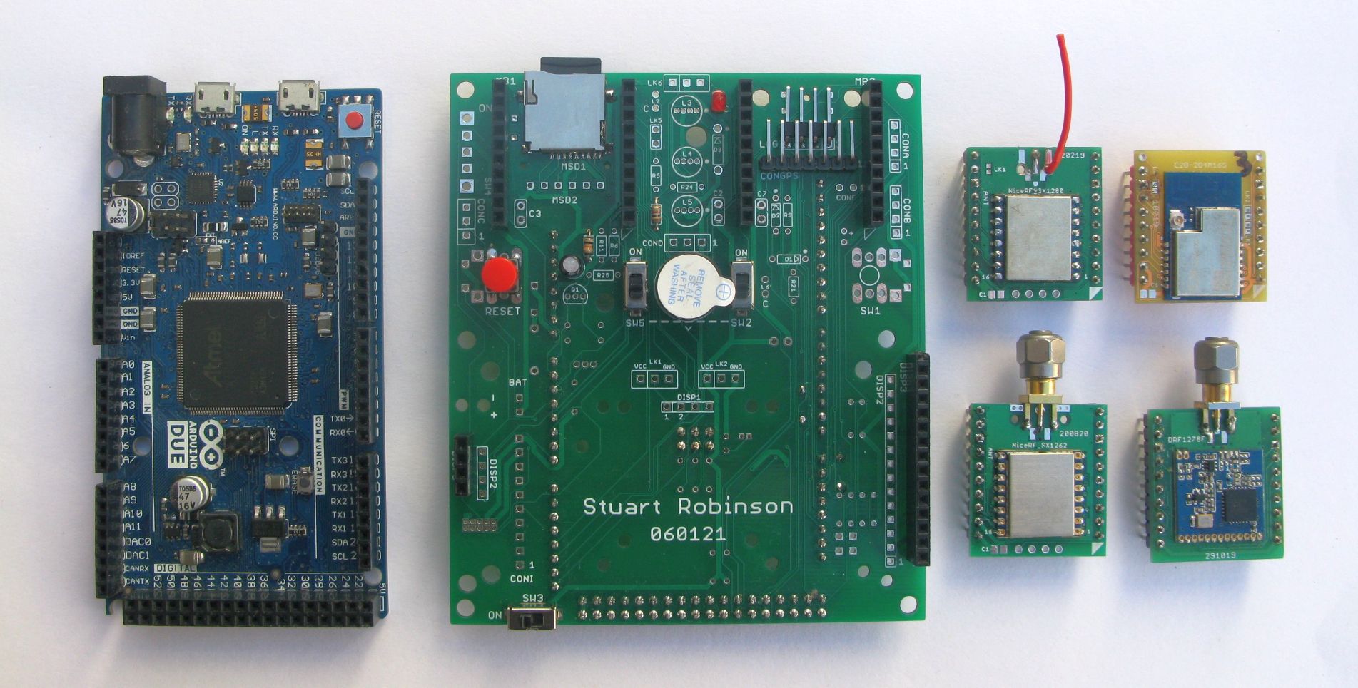
I needed some hardware that was a bit faster than my normally used Pro Minis and that would interface easily with an SD card. I choose to use an Arduino DUE as the basis for a shield PCB. DUEs are fast with plenty of memory and low cost too.
The picture below shows the Arduino DUE, shield PCB and a selection of LoRa modules. The PCB has header sockets fitted for a couple of plug in modules, a ILI9341 TFT touch display, a LED and buzzer, plus a micro SD card holder. The LoRa modules are 2.4Ghz LoRa (SX1280) and 434Mhz LoRa (SX1262 and SX1276).
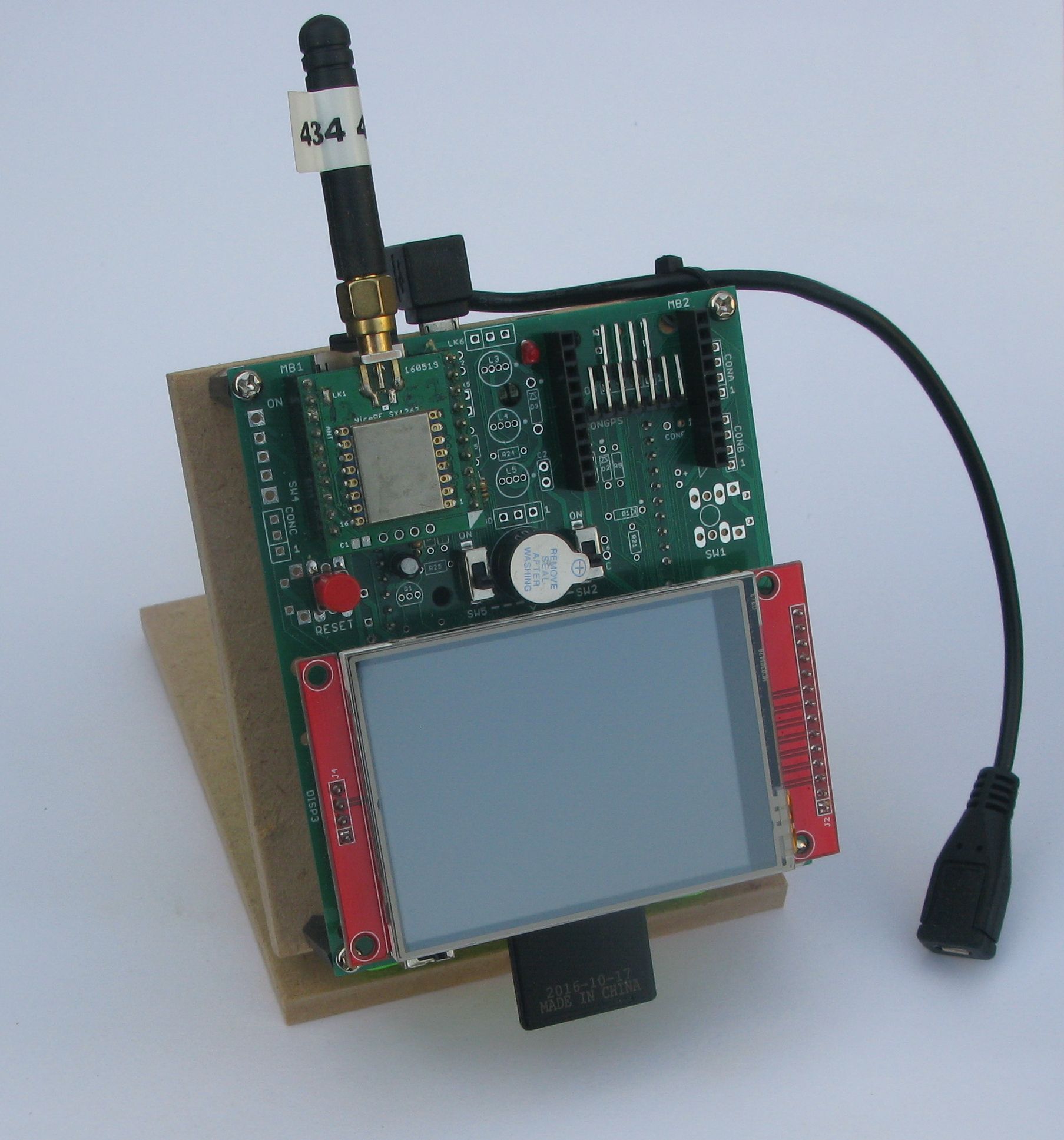
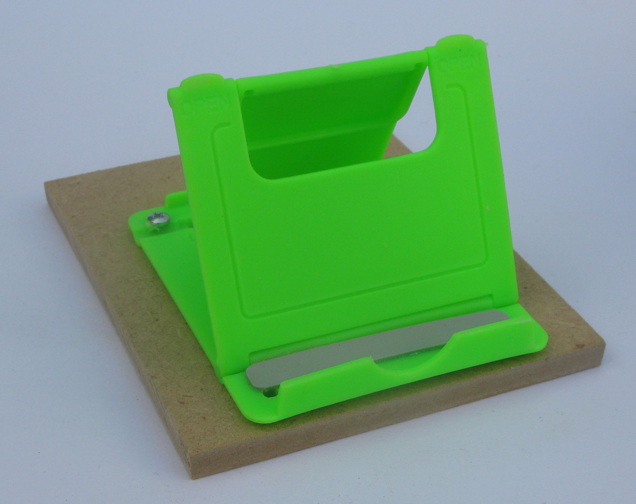
I cut up a couple of bits of MDF so I could have the shield on my desk at a convenient angle using one of those cheap mobile phone stands.
microSD card holders
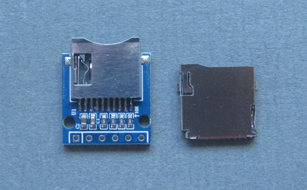
Please take care with the type of microSD card holder you use. The common type of holder that is designed for use on 5V logic level Arduinos should not be used when there is another SPI device on the bus, such as a LoRa module, the SPI bus wont work.
Use a microSD card holder type that has no regulator or logic level converters. The microSD card holders I used for the DUE board shown above are pictured below, pin in hole type on the left, SMT type on the right;
I next wrote some standard functions that provided a common interface for the SD card, either the ILI9341 displays SD card or the shield PCB microSD card holder and put the functions in a file called SDlibrary.h so it could be easily included in an Arduino sketch. This was the list of functions I came up with as being required;
bool SDLib_initSD(uint8_t CSpin);
uint32_t SDLib_getFileSize(char *buff);
void SDLib_printDirectory(uint8_t numTabs);
uint32_t SDLib_openFileRead(char *buff);
uint16_t SDLib_getNumberSegments(uint32_t filesize, uint8_t segmentsize);
uint8_t SDLib_getLastSegmentSize(uint32_t filesize, uint8_t segmentsize);
bool SDLib_openNewFileWrite(char *buff);
uint8_t SDLib_readFileSegment(uint8_t *buff, uint8_t segmentsize);
uint8_t SDLib_writeSegmentFile(uint8_t *buff, uint8_t segmentsize);
uint16_t SDLib_fileCRCCCITT(uint32_t fsize);
The header array would need to be read and filled with variables so I also wrote a series of routines that would move the appropriate variables to and from the header array, this is an example of the receiver reading the header array that the transmitter has sent;
void readRXHeaderValues()
{
  	RWarray_begin(header, 0);
  	PacketType = RWarray_Readuint8();
  	flags = RWarray_Readuint8();
  	headerL = RWarray_Readuint8();
  	dataarrayL = RWarray_Readuint8();
  	networkID = RWarray_Readuint16();
  	RXcrc = RWarray_Readuint16();
  	filelength = RWarray_Readint32();
}
I set up an example program that would send an image file in segments with the fastest LoRa settings the SX128X would allow, SF5 and bandwidth 1600Khz. The transmitter would open the indicated file name on the local SD, get the file size and work out from the given segment size how many segments there were to send and the size of the last segment. The transmitter then sends an open file request to the receiver which when it had opened the same file name for writing on its SD card would then respond with an acknowledge. The transmitter would then proceed to send all the segments in sequence waiting for an acknowledge each time.
When all the segments had been received and acknowledged, the transmitter would send a file close to the receiver which would then close the file write, take a CRC of the completed file and return this CRC to the transmitter as an acknowledgement.
For the 2.4Ghz LoRa settings mentioned above my sample image file, see below, which has a file length of 63091 bytes took 8.5 seconds to get from the transmitters SD card to the receivers, not bad.
For maximum transfer speed some fine tuning of the process is needed and it depends on the LoRa settings in use. Both transmitter and receiver need to switch quickly between transmit and receive modes. The transmitter once it has sent a segment needs to switch across to receive mode to listen for the acknowledgement. The period it listens needs to be configurable to allow enough time for the acknowledgement to finish transmitting. If the program waits too long a transfer with missed packets could slow right down due to the time retries would take. Then the receiver when it has received and checked a incoming segment needs to switch to transmit mode and send the acknowledgement. At this point in time the transmitter needs to be ready to receive, so its possible a slight delay in sending the acknowledge is needed. Thus these two parameters, the wait for acknowledge time-out at the transmitter and the delay in sending the acknowledge at the receiver need to be configurable parameters and selected for the LoRa parameters in use.
With the program working well on an SX1280, it was straight forward to port the software across to the UHF SX126x device library, the software interface for these devices are very similar.
The fastest LoRa settings for a UHF (434Mhz) SX1262 are Spreading Factor 5 (SF5), bandwidth 500Khz and coding rate 4:5. With these settings the SX126x set-up took 15.9 seconds to transfer the 63091 bytes file. These LoRa settings are relatively short range (for UHF LoRa) so I next looked at the impact of using longer range settings.
The duty cycle problem
The duty cycle problem rears its head here, although in fast mode the image could be sent in around 16 seconds, at 10% duty cycle you could only send one image every 160 seconds and at 1% duty cycle only one image every 1600 seconds or 26 minutes ! Oh dear.
If you search around the frequency allocations for your part of the World you will often find a band where you can use 100% duty cycle, in the UK there is such an allocation in the 434Mhz band but the channel (bandwidth) must be below 25Khz. The common SX127X devices can with a bit of fiddling be persuaded to operate at a bandwidth of 20.8Khz. Two standard SX127X devices will struggle to communicate at this low bandwidth as the frequency tolerance between modules is then only 5200hz, so two SX127x devices may not communicate at this frequency even when both are at the same temperature. The SX126x modules however come with TCXO support as standard and these are fitted to most manufactured modules. The TCXO solves the interoperability problem at low bandwidths and two SX1262 devices are happy to communicate at the lowest possible bandwidth of 7.8Khz, even when there are wide temperature differences between modules. So I set up some SX1262s to communicate at SF5, bandwidth 20.8Khz, coding rate 4:5. The 63091 bytes image took 253 seconds to send, so its not fast, but remember you could send images continuously.
SF5 is for SX126X only, at SF6 which is supported on SX127X (not withstanding the frequency error issues) and bandwidth 20.8Khz the sample image took 406 seconds to send.
Summary of image transfer times - 63091 bytes image file
| No. | LoRa Module | Frequency | Spreading Factor | Bandwidth | Time Seconds |
| 1 | SX1280 | 2.4Ghz | SF5 | 1600Khz | 8.5 |
| 2 | SX1280 | 2.4Ghz | SF12 | 400Khz | 936 |
| 3 | SX1262 | 434Mhz | SF5 | 500Khz | 16 |
| 4 | SX1262 | 434Mhz | SF7 | 500Khz | 50 |
| 5 | SX1262 | 434Mhz | SF5 | 20.8Khz | 245 |
| 6 | SX1262 | 434Mhz | SF6 | 20.8Khz | 406 |
| 7 | SX1262 | 434Mhz | SF7 | 20.8Khz | 695 |
In the table above simple communications (i.e. not large scale data transfers) at the setting for No.2 worked in a high altitude balloon test at 80km+. And way back in 2015 the settings used in No.4 worked at 100km, both tests using 10dBm transmit power.
All the file transfer tests above were done on the bench, unfortunately at the moment (March 2021) the reasons I can leave the house are very limited due to Covid-19 restrictions.
What next ?
Before updating the SX12xx Github library with the new functions and file transfer examples, I need to go back to the ESP32CAM. The example programs need to send the ESP32 memory buffer that is the image rather than reading the image from the SD drive.
Stuart Robinson
April 2021