Adding an LCD display to tracker receiver
![]()
The SX12xx Library example GPS tracker receiver program ‘25_GPS_Tracker_Receiver_With_Display_and_GPS.ino’ is a fully working tracker receiver program that will receive the LoRa transmissions from the tracker transmitter at very long distances, hundreds of kilometres if you have clear line of sight.
The display used for the original tracker receiver program was a small I2C connected OLED, these are low cost and there is only 4 wires needed to connect them to the host micro controller. The host micro controller used for both the transmitter and receiver was the Easy Pro Mini Controller.
Unfortunately these OLED displays are next to useless for real tracking applications when outdoors during the day, especially if the sun is out, they are nowhere near bright enough to see.
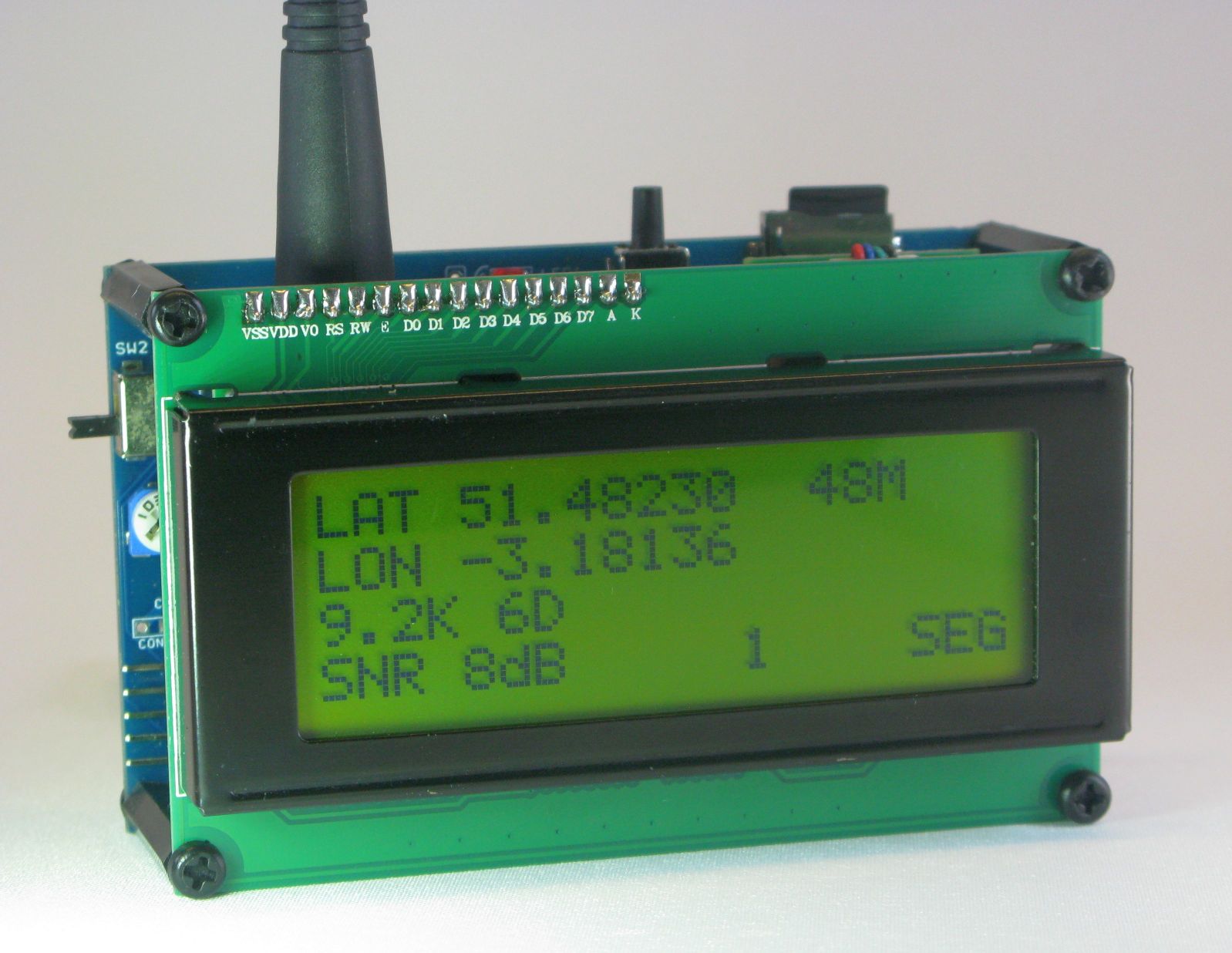
For a useful outdoor tracking you really need to switch to a transflective type LCD which are highly readable even in direct sunlight. There are several versions of the 20x4 LCDs out there, the blue ones are not that visible outdoors but the yellow looking transflective ones are very good. The picture below shows what these displays look like. For direct connection to the Easy Pro Mini boards you will need the 3.3V version of the display.
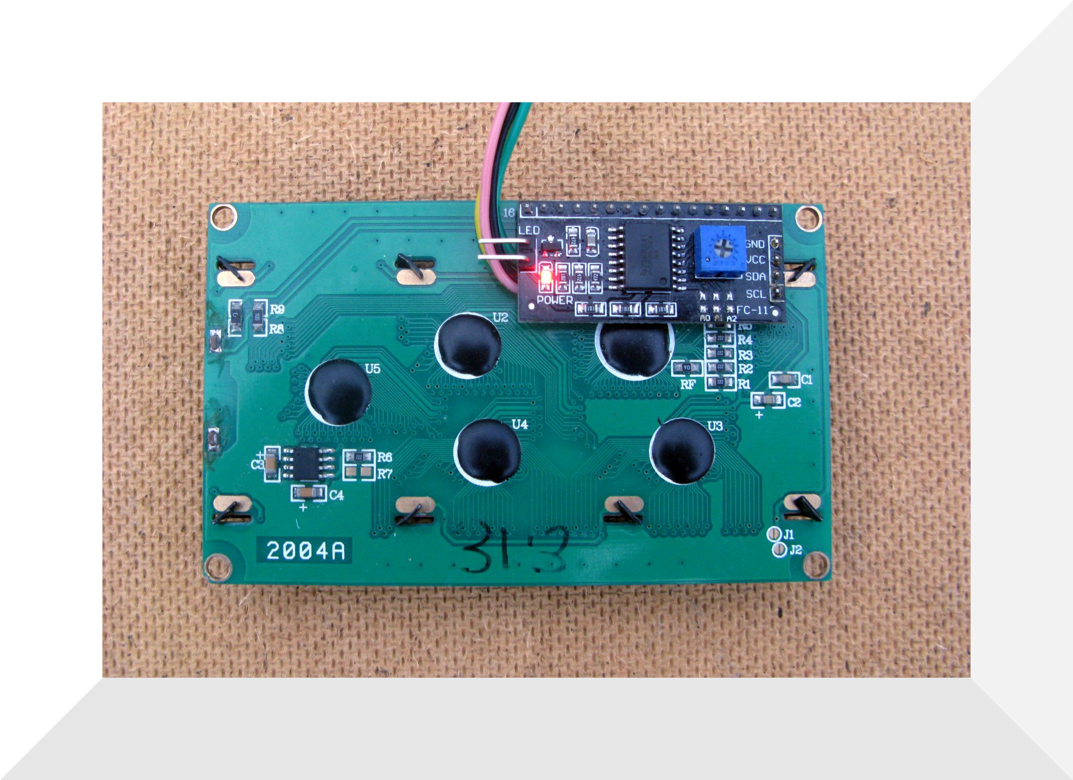
The LCDs displays are based on the HD44780 controller and normally need some 7 IO pins to drive them. There are add on boards readily available that use a PCF8574 LCD backpack to drive the display, so the only connections needed to the hose controller are GND, +V (3.3V) and SDA and SCL I2C signals, so 4 wires in all. These adapters solder onto the pins on the LCD display, see the picture below.
Modified Receiver Program
The original tracker receiver program was changed to use the 20x4 LCD with the screen layout adjusted to fit the important bits on the screen. This program is called 25A_GPS_Tracker_Receiver_With_LCD_Display_and_GPS and is in the \examples\SX127x_Examples folder of the SX12xx Library.
The screen layout for the modified receiver program is shown below.
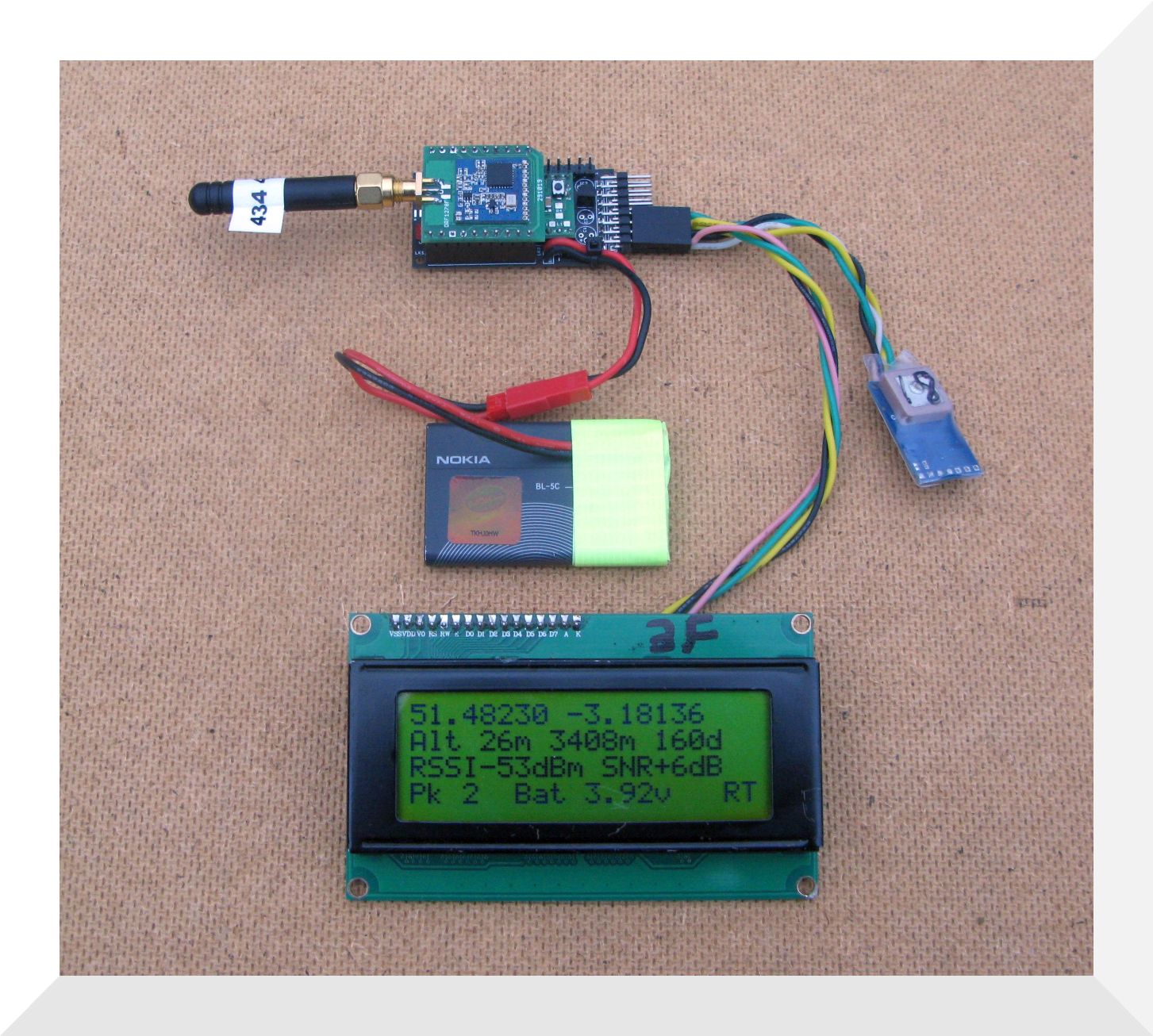
Latitude and Longitude are on the first line.
On the second line altitude in metres, then distance and direction to the remote tracker. The distance and direction only displays if the the tracker receiver has its own GPS that then has a fix.
Third line has the RSSI, signal strength, in dBm, the signal to noise ratio (SNR) of the received signal.
The bottom line shows a count of packets that loops from 0-255. Its purpose is to indicate if your still receiving from the tracker, if the count is not going up your not receiving signals. Also an the last line is the battery voltage and the RX and TX GPS fix indicators.
Rather than clear the whole display every time there is a new fix from the receiver GPS or a tracker packet is received, the display is cleared one line at a time which reduced screen flicker.
Resilience features
There is the possibility that you have received a location packet from the tracker but that the tracker then stops transmitting, your RC plane has crashed maybe.
The receiver does remember the trackers last location so that as long as the receivers GPS is working you will get an updated distance and direction to the tracker. So you can just wander around till the distance to the tracker reduces or use a map and compass to work out where the last tracker location is on a map.
However if you drop the receiver or the batteries go flat the trackers last known location can be lost, not good.
To work around this potential problem the receiver can use a Ferroelectric RAM (FRAM) to store the last received tracker GPS location. The FRAM is non-volatile storage so the data is available after a power down. The ATmega328P processor used for the tracker receiver does have 2kbytes of EEPROM, but it has a limited endurance or limit to the number of writes. If you had a tracker sending its location very rapidly, say every 1 second then the EEPROM would exceed its number of writes (100,000) in
28 hours. Accepted that once a second is a very fast rate, but its wise to allow for most eventualities. The FRAM however has a write endurance of at least 10,000,000,000 times, and some FRAMs have an endurance 10,000 greater than this. So at this 1 second update rate a FRAM would last at least 317 years.
The modified program has the option of using either EEPROM (at your own risk) or FRAM to store the tracker location. The Easy Pro Mini board shown above can be fitted with a MB85RC16PNF (2kbyte) or FM24CL64 (8kbyte) FRAM, both are 8 pin SOIC devices.