Power measurements can be useful !
A previous blog post looked at how you can use a cheap (£20) power meter to make accurate measurments on the power output of LoRa® radio devices.
I was following the guide and program for a creating a simple TTN node that Andreas Spiess presented in a video;
https://www.youtube.com/watch?v=duwUwXt-hs8
The program provided uses the LMIC library. The program works fine and the packets show up in the TTN device console.
I wanted to add some of my own diagnostics, so I borrowed some routines from my tracker software thats reads back the LoRa® device registers after a packet send and displays the frequency, bandwidth, spreading factor, coding rate and power level the LoRa® device was set to.
I had assumed the power level for a TTN node would be set to 14dBm/25mW due to legal restrictions, but the LoRa® device was inmdicating it was s set to 16dBm/40mW .
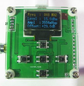
I knew that my ‘calibrated’ 868mhz LoRa® module was about 1dBm below the power it should be (see the previous blog post) so I hooked that module and the TTN node software to the power meter. The node program copde was set to send a SF12 packet at start up so there would be enough time for the power meter to display it.
The power meter displayed 15dBm, which is consistent to it actually being programmed for 16dBm as my diagnostic code had suggested.
Now the appropriate register for power level is RegPaConfig and its set in radio.c of the LMIC library;
static void configPower ()
{
#ifdef CFG_sx1276_radio
// no boost used for now
s1_t pw = (s1_t)LMIC.txpow;
if (pw >= 17)
{
pw = 15;
} else if (pw < 2)
{
pw = 2;
}
// check board type for BOOST pin
writeReg(RegPaConfig, (u1_t)(0x80 | (pw & 0xf)));
writeReg(RegPaDac, readReg(RegPaDac) | 0x4);

#elif CFG_sx1272_radio
// set PA config (2-17 dBm using PA_BOOST)
s1_t pw = (s1_t)LMIC.txpow;
if (pw > 17)
{
pw = 17;
} else if (pw < 2)
{
pw = 2;
}
writeReg(RegPaConfig, (u1_t)(0x80 | (pw - 2)));
#else
#error Missing CFG_sx1272_radio/CFG_sx1276_radio
#endif /* CFG_sx1272_radio */
}
I have CFG_sx1276_radio selected so the power level is set by this line of code;
| **writeReg(RegPaConfig, (u1_t)(0x80 | (pw&0xf)));** |
Which writes the pw variable into the power setting register. If pw is 14 (for 14dBm?) the power level of the device is according to the datasheet;
Pout=17-(15-OutputPower). ‘OutputPower’ is what is written to bits 3-0 of RegPaConfig and if its 14 the actual power level selected appears to be;
Pout=17-(15-14) = 16dBm.
This is in line with my diagnostic print, which suggests the power level is being set to 16dBm when 14dbm is expected.
Is it possible the LMIC code should be;
| **writeReg(RegPaConfig, (u1_t)(0x80 | (pw&0xf)-2));** |