Adventures with the ESP32
As part of a project to check if locally generated electromagnetic interference (EMI) would affect LoRa® receiver performance at its weak signal limits I needed a ESP32 board that I could plug in various modules into. Faster micro controllers, such as the ESP32 are becoming the norm, which is understandable, they are cheap, fast, have lots of memory and in the case of the ESP32, have built in Wifi and Bluetooth. Faster micro controllers, however, generate more EMI, so I wanted to do a LoRa® reception comparison with various micro controllers. For the comparison to be valid I needed to use the same LoRa® module for different controller boards, the easiest way to achieve that was to have the LoRa® device on a plug in board.

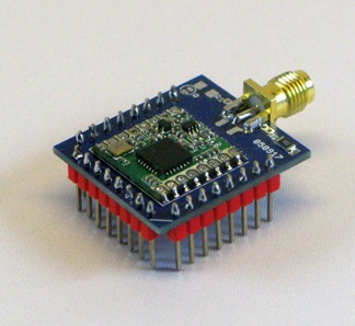
The RFM98 module above is assembled using my own low cost PCBs, in this case the module PCB is modified from standard to allow access to all the LoRa® device DIO pins. The advantage of having a controller board that accepts my breadboard friendly modules is that it is easy to re-purpose the controller board simply by fitting a different type of module, see the Mikroelectronica link above for the possibilities.
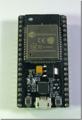
But which ESP32 board to use ? There are several, the Wemos Lolin 32 seems popular, but I really wanted to be able to plug in a choice of batteries and not be restricted to a Lithium battery. The NodeMcu32s fits the bill, its one of the smaller ESP32 boards and provides access to the voltage(battery) in pin. The board is shown below.

Designing a PCB for the NodeMcu32s was easy enough, I use Eagle, but what had me stuck was which of the pins of the NodeMcu32s you could you use as inputs, outputs, interrupts or analogue and more importantly which pins did you need to avoid using for fear of interfering with the ESP32 itself or the attached flash.
I decided to design my board layout first and then check that I could get the functions I wanted out of the pins, the functions I needed were;
Outputs, flash an LED, drive a chip select.
Inputs, read a switch or interrupt.
Analogue, read a battery voltage for instance.
Pulse Width Modulation, not needed for my board, but useful for the sockets to take the breadboard friendly modules.
UART transmit and receive, two channels.
I2C, read and write to a FRAM and SSD1306 OLED display
Micro SD card read and write.
LoRa® device, read and write
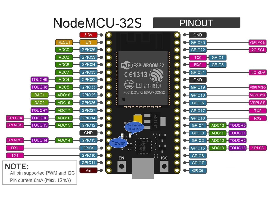
So as well as checking the basic pin functions, I needed test programs for each of the above to confirm it would all work in practice. After a couple of days of testing and checking I worked out which pins you can use on the NodeMcu32s and which ones to avoid, they are listed below, with comments against each pin.

0 Input, shared with the IO0 switch on the board, this switch needs to be pressed, pin held low, to download a program
1 TX output from serial console, I made no connection to this pin
2 Output, shared with the LED on the board
3 RX input to serial console, I made no connection to this pin
4 Analogue, used to read battery level
5 Output, SPI SS, used for chip select on LoRa® device
6 Could not use, appears to be used by flash
7 Could not use, appears to be used by flash
8 Could not use, appears to be used by flash
9 Could not use, appears to be used by flash
10 Could not use, appears to be used by flash
11 Could not use, appears to be used by flash
12 Input, can be used as a switch input, but be sure to leave it floating during programming. There is a pull up to VCC on the board and when this pin is high the correct voltage for the Flash is selected. If the pin is low programming will fail
13 Input, Serial1 RX, you can select any of the available input pins for the RX when defining the Serial1 instance
14 Input, Serial1 TX, you can select any of the available input pins for the TX when defining the Serial1 instance
15 Input and Output, LoRa® device DIO2 interrupt input or PWM output
16 Input, Serial2 RX, you can select any of the available input pins for the RX when defining the Serial2 instance
17 Output, Serial2 TX, you can select any of the available input pins for the TX when defining the Serial2 instance
18 Output, SPI SCK, used for the LoRa® device and SD card
19 Input, SPI MISO, used for the LoRa® device and SD card
21 SDA, used for the SSD1306 display and I2C FRAM
21 SCL, used for the SSD1306 display and I2C FRAM
23 Output, SPI MOSI, used for the LoRa® device and SD card
25 Output, used for chip select on SD card
26 Analogue, used to read battery level
27 Output, used for the RST on the LoRa® device
32 Output, PWM
33 Input only, used for used for reading external switch
34 Input only, needs external pull-up, used for reading DIO1 on LoRa® device
35 Input only, needs external pull-up, used for reading DIO0 on LoRa® device
36 Input only, needs external pull-up, used for reading DIO3 on LoRa® device
39 Input only, needs external pull-up, used for reading external switch
EN Input, External reset, pull to ground for reset.
VIN External power input. Intended supply is 4 x AA Alkaline or NiMh batteries.
It is not clear why pins 6 to 11 are provided on the board, you do not appear to be able to use them. These pins are not present on some other ESP32 boards such as the Wemos Lolin32.
Although the pin mappings above are the defaults for the NodeMcu32 board you can map the pins for SPI, I2C, UART or PWM to any available pins, although not 6,7,8,9,10,11,12. I have also not tried redirecting these interfaces to 34,35,36,37.
There are some capacitors associated with pins 36 (VP) and 39 (VN) but they did not appear to interfere with the relatively slow interrupts you will get from a LoRa® device for instance.
Program space
I have a program that I use for LoRa® link testing, it receives LoRa® packets and logs the SNR, RSSI and contents to the Serial monitor and SD card. When compiled for an Arduino Pro Mini the program consumes this much space;
Sketch uses 19562 bytes (63%) of program storage space. Maximum is 30720 bytes.
Global variables use 1292 bytes (63%) of dynamic memory, leaving 756 bytes for local variables. Maximum is 2048 bytes.
For the NodeMcu32s it consumes this amount of space;
Sketch uses 159701 bytes (12%) of program storage space. Maximum is 1310720 bytes.
Global variables use 12348 bytes (4%) of dynamic memory, leaving 282564 bytes for local variables. Maximum is 294912 bytes.
So although the NodeMcu32s reports as having 1,310,720 bytes of available Flash, compared to 30,720 for the Pro Mini, compiled ESP32 programs consume that space at around 8 times the rate for an ATMega328 program, so you don’t have as much usable program space as you might think.