The impact of bandwidth on LoRa® sensitivity.
A LoRa® device provides several options if you want to improve the reception range of the packets you are sending. All of these ‘improvements’ apart from increasing transmitter power result in slower packets that take longer to send.
The options are;
Increase transmitter power
Increase the spreading factor (SF)
Reduce the bandwidth
Increase the coding rate
What I want to measure is the real world effect of reducing the bandwidth.
For a LoRa® receiver to detect (capture) a packet, the transmitter and receiver centre frequencies need to be within 25% of the bandwidth of each other, that’s according to the data sheet. Myself I would err on the cautious side and plan for 20%, which I have found is closer to real world conditions.
So what does the 25% capture range mean?
Assume the transmitter has a centre frequency of 434Mhz and we are using a LoRa® bandwidth of 500kHz. 25% of this is 125kHz, so as long as the receiver centre frequency is +/- 125kHz of 434Mhz, then the receiver should pick up the packets. Thus the receiver centre frequency need to be within the range of 433.875Mhz to 434.125Mkhz.
A lot of LoRa® modules do not use temperature compensated crystal oscillators for their reference frequency but use low cost plain crystals instead, this helps to keep the cost of LoRa® modules low. In practice I have seen 434Mhz LoRa® modules at most +/- 5khz from 434Mhz, which is not bad for low cost crystals.
However one module might be up to 5kHz high, and another might be 5khz low, so the difference between two modules could be as high as 10kHz. Using the 25% of bandwidth rule you could have a situation where out of the box two LoRa® modules might not communicate with each other at 41.7Kz bandwidth, and this has happened to some of the modules I have used. Its for this reason, and to significantly improve interoperability of devices, that The Things Network (TTN) and LoRa®WAN typically use a bandwidth of 125kHz, it’s then unlikely that two devices will be far enough apart in frequency that communications fail.
Calibrating LoRa® modules with a compensation factor, so that variations in centre frequency are eliminated, for a particular temperature, can allow lower bandwidths to be used. You do though need a frequency counter or similar to measure the centre frequency of each individual module.
Fortunately the LoRa® device will, on reception of a packet, calculate an estimate of the frequency error between transmitter and receiver so it is possible for the receiver to track any transmitter frequency changes due to temperature shifts even at low bandwidths. Although do note that this AFC functionality will only work once packet reception has started ……….
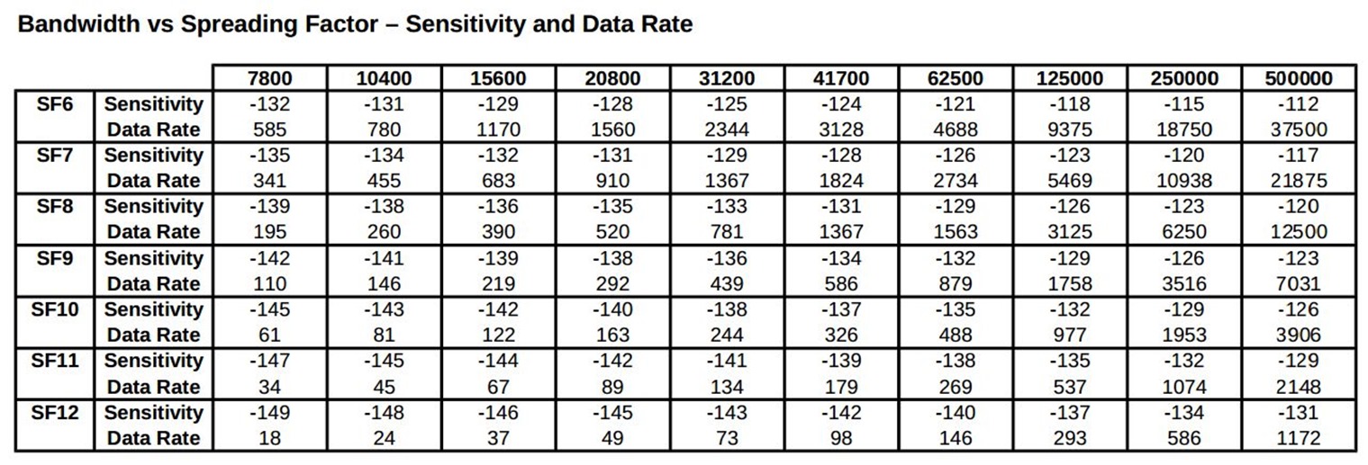
Enough preamble ….. what I really wanted to measure was how much sensitivity improved as the bandwidth was reduced with the spreading factor kept the same. The table below shows the quoted sensitivity in dBm for a LoRa® device and the data rate for the range of spreading factors and bandwidths.

In the test I carried out, I was using a spreading factor of 8 and a bandwidth of 7.8kHz versus 62.5kHz, the table shows that at 62.5kHz the sensitivity should be -128dBm improving to -139dBm at a bandwidth of 7.8kHz. The test I would use would not measure sensitivity itself, but rather how much transmit power was required to cover a link for each of the bandwidths. The quoted data sheet sensitivity is not so important, but how much power you actually need to cover a particular distance is.
I set up my ‘typical’ 1km across town link so that at the bandwidth of 62.5kHz SF8, packet reception stopped when the transmitter power was around 14dBm. The transmitter antenna needed a 20dB attenuator fitted to achieve this, so in this case the 1Km was achieved with -6dBm of actual transmitted signal.
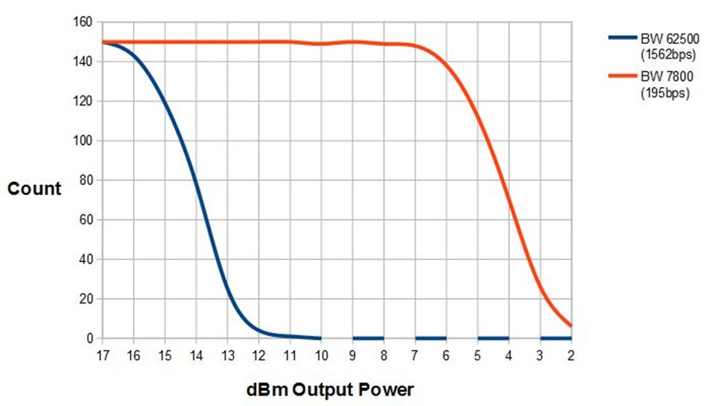
The test software sent 62.5kHz bandwidth test packets at 17dBm down to 2dBm in 1dBm steps, then flipped across to a bandwidth of 7.8khz and did the same. Automatic frequency control operated at the receiver and kept it within 250Hz or so of the transmitter, and gave reliable reception at the lower bandwidth.
The results are shown in the graph below, it shows how many packets of a particular power were received;

The data sheet predicted a 10dBm improvement as the bandwidth changed from 62.5khz down to 7.8kHz and that is close to what the graph shows. Note the data rate dropped from 1563bps to 195bps. The 10dB improvement would represent a range improvement of around 3 times.
So what’s the point of low bandwidth?
An interesting question.
With bandwidths lower than 62.5kHz, you cannot assume that a transmitter and receiver will work together, due to changes in centre frequency. Calibration can help, but if one end of the link is very cold then the frequency could shift enough to stop the initial reception, so why bother?
There are two basic ways to improve LoRa® link performance or range. First is to use a higher bandwidth and spreading factor, the other is to use a lower bandwidth and spreading factor.
Starting from a 62.5kHz bandwidth SF8 set-up you get around the same increase in performance and data rate by changing to SF12 as you would by staying at SF8 and reducing the bandwidth to 7.8kHz.
In a lot of places around the world, if you keep below a 25kHz channel you can use up to 100% duty cycle, I.e transmit continuously. Above 25kHz channels, or LoRa® bandwidths above 20.8kHz, duty cycle may be limited by regulation to 10%. SF12 at a higher bandwidth might give you the same range as a lower bandwidth and spreading factor combination, but you may be significantly restricted by duty cycle as to how much data you can transmit in a given period.
So if you want to send a lot of data, that needs more than a 10% duty cycle it makes sense to use a lower bandwidth and spreading factor combination, if you can overcome the frequency capture issues mentioned above.