Ping testing the Heltec Wi-Fi LoRa® OLED device
This Heltec device looks very promising, it’s and ESP32 module with built in LoRa® device Wi-Fi, Bluetooth and a OLED display to boot!

I have tested some other micro controller modules where the faster processor produces enough electromagnetic interference (EMI) to reduce the LoRa® sensitivity. This problem does not affect installations where the LoRa® device antenna is remote to the micro controller, such as with a roof mounted antenna, but there is an effect if the LoRa® antenna is local as it will be for a portable device or a small sensor node.
With some simple equipment it is not difficult to test for any adverse affect, and we can measure this effect in dBm.
To carry out a ping test you need a LoRa® transmitter that repeatedly sends packets at the frequency, bandwidth, spreading factor and coding rate that you specify. The test is best performed in a large open field, to reduce the impact of external interference, from PCs, lights, Wi-Fi and reflections from nearby objects.
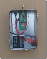
The ping test requires that you reduce the reception range of the packets to around 100m or less. This can be achieved by shielding the transmitter in a metal box and using attenuators in series with the antenna to significantly reduce the transmitted signal level . Even a SMA terminator may radiate enough signal to work. For the Heltec device comparison the transmitter, an Arduino ATMega Pro Mini and Hope RFM98 LoRa® device were placed in a tin on a pole in the middle of the field.
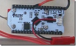
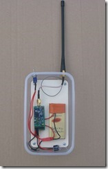
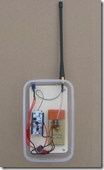
Below, left to right, transmitter, ATMega receiver and Heltec receiver.


The receiver used to set-up the test is also an Arduino Pro Mini and Dorji DRF1278F LoRa® device. It is set-up with the same LoRa® parameters and has an LED and buzzer which activate whenever a packet is received. The transmitter is sending packets every second or so.
With the receiver in your hand you walk away from the transmitter until the LED\Buzzer stops. If you get 100m and your still receiving packets, you need to attenuate the transmitter some more and try again.
Lets imagine we have now set it up so the packets stop being received at 100m when the. Arduino Pro Mini receiver is used.
We then repeat the test, either with a different type of receiver, or perhaps a different transmitter or receiver antenna. This time the LED\Buzzer stops at 50m. So the reception distance in the first test is twice the second, and we know that twice the distance requires 4 times or 6dBm more power.
Thus by simple distance measurement we can conclude that the antenna (or receiver) used in the first test is 6dBm better than in the second. This technique for making dB measurements works if only one antenna is changed at a time, the receiver antenna is held at the same height and orientation for both tests, and the area for testing is large enough so that reflections from near objects are minimal.
Over to the local park I went and set-up the test as described above, the transmitter with an SMA terminator fitted and the lid missing from the box gave me 108m. LoRa® settings were 434.4Mhz, bandwidth 125000, spreading factor 8, coding rate 4:5.
I then changes to the Heltec Wi-Fi LoRa® receiver and repeated the test, I received packets up to 70m. Thus the Heltec board had circa 3.5dBm worse receiver performance.
Now although the test showed the difference between two receivers, its possible that the LoRa® device on the Heltec board was below par. You could of course test a number of modules to get an average result, but that could get expensive. There is an alternative however, use the same LoRa® device to test first with the ATMega receiver and then with the Heltec ESP32 board. When I have suitable breadboards to build these receivers, I will repeat the test.