At Last ………
At last I have a LoRa® tracker receiver that works well with very weak LoRa® signals and is easy to put together. The receiver is based on Arduino and an ATMEGA 1284P with the entire board running on 3.3V and no interference creating switching power supply in sight.
The receiver can be used as both a highly portable tracker receiver and a desktop terminal application with remote control of the tracker. There is logging of received packets to SD card, a Bluetooth uplink into an Android mapping application, audio uplink of high altitude balloon payloads into FLDIGI, plus a facility to program the receiver over the air to match (bind to) the transmitter settings. There are 3 display options, Nokia 5110, ST7735 TFT and SD1306 OLED. The last local GPS fix and remote fix for the tracker is saved and always available when the receiver is switched on. Thus you can be use the receiver to guide you (distance and direction) to the trackers last known location.
With a Low Drop-out voltage regulator fitted the receiver can run from 3 x AA Alkalines, 4 x AA NiMh or a single Lithium Ion battery.
The board is a modular design with two sockets to take my breadboard friendly modules so whilst I am using it here as a LoRa® Tracker receiver, with a LoRa® device in one socket and a GPS in the other, it can be used with other MikroElectronica Click modules, with the exception that in portable mode there is no 5V supply.
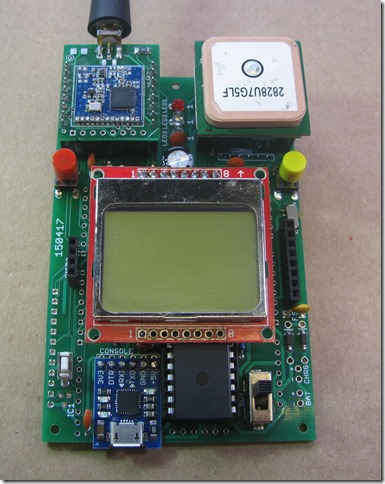
My LoRa® tracker software has had a thorough review and now all the routines for LoRa®, GPS, Display etc. are common across the new receiver, HAB tracker, lost model locator and remote sensor applications.
To test the sensitivity of the receiver and compare the performance when it was powered with a battery and via a switching 5v supply as provided by a typical USB power bank, I used my link test software, the transmitter part of the link test is ideal for this purpose.
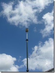
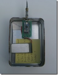
The program was configured to transmit a short test packet descending in power from 17dBm to 2dBm. The packet contains the power level at which it was transmitted. The transmitter is put in a metal box, so that the only signals getting out are through the antenna, and a 20dB attenuator fitted in line with the ¼ wave wire. The transmitter then goes on the mast in my garden.
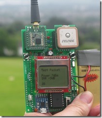
I went to my favourite testing place in the North of Cardiff, it overlooks the city and is around 4km from my home.
At the testing place the Tracker receiver software picks up the test packets and displays them on screen, you can readily tell the power with which the packet was transmitted.
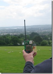
With the Lithium battery I was receiving some packets that were being sent at 2dBm, but remember the 20dB attenuator on the transmitter, so the ERP of the packet was -18dBm.
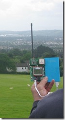
With the USB power bank powering the receiver, I just received some packets sent at -3dBm, but very little else. So the power bank (or presumably its switcher) was loosing me around 15dB in LoRa® performance, which is a lot, the reception distance would be around 1/6th of the Lithium battery powered receiver.
There is a reasonable relationship between transmitted power and distance. So based on an assumption that I would have received the 3dBm transmitted (-17dBm ERP) packets, what would be the signal gain if no attenuator and the license exempt power maximum of 10dBm was used ? Also assume that in a typical base station receiving application you are likely to use an omni directional gain antenna of approximately 5dB gain.
So the full improvement would be (10-3) + 20 + 5 dBm = 32dBm.
That equates to around a 40 times distance improvement, so a range of 40 x 4km = 160km could be expected in this set-up.