Searching With LoRa - Lost Something?
A series of investigations and experiments to see how good LoRa® technology would be for locating things that are lost.
One of the potential applications for LoRa that interests me is as a tracker for locating things that are lost, be they balloons, radio control models or whatever.
This article describes a series of tests I have carried out as to the effectiveness of the new LoRa transceivers for transmitting the GPS co-ordinates of something that is lost and you need to find.
Frequency Shift Keying (FSK) transmitters such as the RFM22B have been used for tracking for some time but whilst you could use them for sending telemetry, at the typical 10mW power limit of license exempt transmitters, the ground range was quite poor, 100M or less in some situations. These FSK devices could however be used to send out FM audio tones that could be picked up on a low cost UHF hand-held receiver. Using direction finding techniques, body fade or with a directional antenna such as a yagi, these tone generating trackers give good results, the signals could be heard up to 1km away, even in an Urban area.
LoRa is new, released by Semtech in 2013 as the SX127X series of devices. A series of tests has shown a range or distance improvement for the data telemetry of between 10 and 30 times over what FSK devices such as the RFM22B are capable of. There are two common LoRa devices, the Dorji DRF1278F and the Hope RFM98, both are around £6 each.
The remarkable range improvements of LoRa are mainly due to its ability to operate at up to 20dB below the local noise level. An FSK transceiver will need a positive signal to noise ratio (SNR) anywhere from +5dB to +10dB or more above noise. In UHF communications is the local noise level that tends to govern the limits of reception, if you have a high local noise level, you need to have stronger signals.
Thus the LoRa receiver can pick up signals that are between 20dB and 30dB weaker than normal FSK receivers are capable of, which is why there are significant improvements in range or distance.
The LoRa devices can be used as a combination tracker, they can send out both audio tones and data telemetry. LoRa devices can also send out FSK data, but that has not been tested.
Searching for Dolly – It ain’t Rocket Science.
Inspired by the (extended) searching for Cindy in the James May’s Toy Stories on UK TV over Christmas 2014, I decided to see how effective the RFM98 LoRa device was at tracking a doll.
The tests were conducted in and around the grounds of Walcot Hall in Shropshire where I happened to be staying over Christmas.

The tracker was my HABAXE2 LoRa based tracker which sends out a full UKHAS compatible payload using LoRa telemetry at BW41.7Khz, SF8 and coding rate 4:5 (1042bps) plus a reduced payload of Latitude, Longitude and Altitude at 41.7Khz, SF12 and CR 4:5 (98bps).
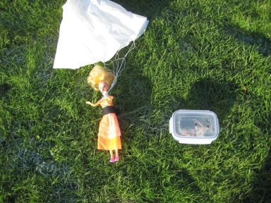
The first LoRa receiver I built was PICAXE and RFM98 based built into a suitable durable hi-tech case, a clip top food container costing £1. This receiver displays the Latitude, Longitude and altitude of the position last recorded by the trackers GPS on the LCD display. This portable receiver can also send out NMEA sentences to its serial port so you can track the location of the remote tracker on a PC Map application, see picture of Dolly with tracker attached and the receiver on the right.
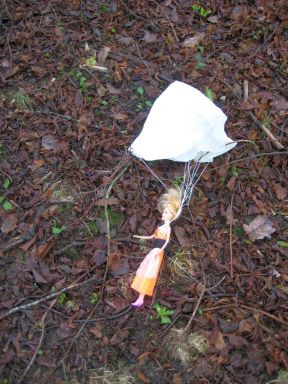
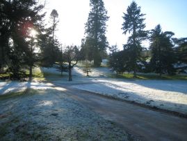
Walcot Hall has an arboretum, a fairly dense bit of woodland around 300M diameter. If Dolly came to ground in this woodland from how far away would the LoRa telemetry (i.e. Dolly’s location) be received? The doll with the tracker attached was placed on the ground at the top end of the wood;
I then walked to the location at the bottom corner of the wood shown by the route 1 on the map;
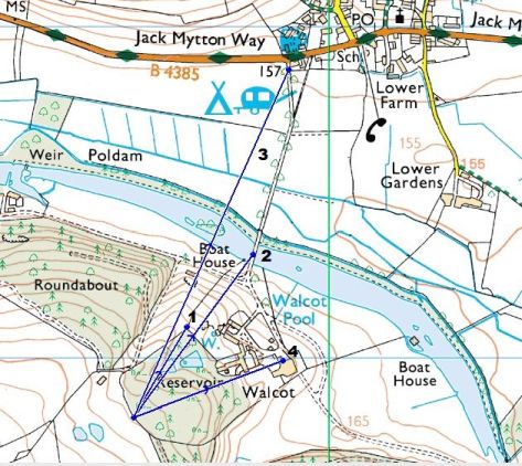
This was 311M away from Dolly. The 1042bps was being received at RSSI -87dBm, +9dBSNR. These are very strong signals, the limit of reception is in the region of -10dBSNR. The tracker is 300M away on the ground in the direction shown in the picture below.
This was with the portable receiver’s small vertical antenna fitted. There was, even at this distance a signal margin of around 19dBm! In fact I could still receive the telemetry with the antenna removed from the portable receiver.
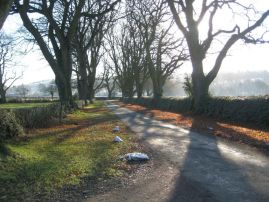
I walked further away towards the Boat House, towards the main road and onto the bridge, route 2 on the map. This was 610M away from Dolly. The 1042bps was being received at RSSI -98dBm, 0dBSNR. The view back to the tracker was the picture below;
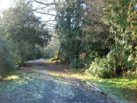
I walked even further away towards the main road, route 3, a distance of 1.15kM from Dolly. The 1042bps was being received at RSSI -93dBm, +4dBSNR. The view back to the tracker was;
Note that at 1.15km, there was still some 14dB of signal margin at 1042bps. Since the 97bps LoRa will operate with a SNR that is 10dB lower, then the receive margin for that rate would be 24dB. Then of course a simple yagi would be expected to provide a further 5 to 10dB of extra signal gain.
At this location I was able to get a direction fix within around 10 degrees on the tracker by aiming the yagi for minimum SNR value or maximum RSSI.
The Dolly tracker also puts out a sequence of tones that rise in frequency but descend in power, thus as you get further away you don’t hear the higher frequency tones. Using the body fade technique for direction finding it was also possible to get a good direction fix on Dolly using a Baofeng hand-held UHF transceiver.
The initial results were very promising indeed.
An Improved LoRa Receiver
The PICAXE based receiver was adequate, but finding the ‘lost’ tracker would be made easier if the receiver could give a direct indication of how far away and in what direction the remote (lost) tracker was. To do this the receiver would need its own GPS, and the micro controller would have to be able to do floating point and trigonometric calculations.
There are several Micro platforms that you could use including Micromite Mk2 or Arduino. I chose to use a Micromite MK2, it runs interpreted Basic is easy to understand and is more than powerful enough for the application.
The component parts of the receiver would be;
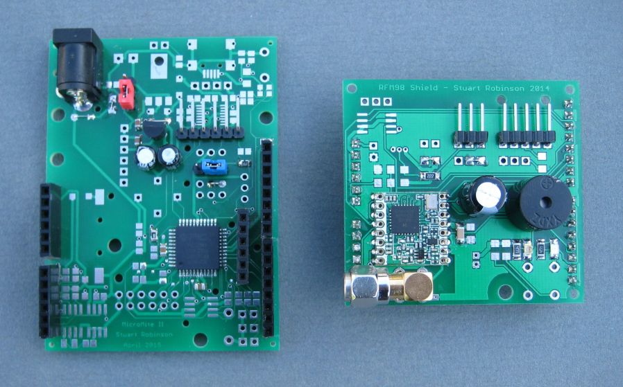
MicroMite MK2 Shield base – Arduino compatible RFM98 Arduino Shield FTDI USB Serial Interface Lithium Ion battery LCD display Case
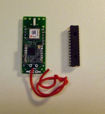
Most of the components on the shield base design, RTC, RAM, Logger, and FTDI etc. are not needed for this LoRa receiver application, so they were simply omitted from the PCB build. This is also the case for the RFM98 shield, some components are not needed, so a redacted build was used.
Pictures of the shield base and shield are below;
Finding a suitable display for this portable receiver was not so easy. The requirement is for a simple display for outdoor use that can display Latitude and Longitude of the receiver and tracker in small text, and the distance and direction in large text, and it must be visible in direct sunlight.
Digole do a range of LCD graphic displays that have backpacks so they can used as serial addressable displays. They are easy to drive, have multiple fonts and some can run from 3.3V, which makes interfacing to the LoRa display easy. However these displays lack contrast, see first picture below, the display is outdoors on a sunny day;
The ILI9341 LCDs that are cheap on eBay these days are very versatile, have lots of pretty colour text and graphics, but not so good outdoors, see picture below;
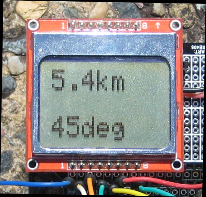
The Nokia 5110 LCDs are hard to beat, great contrast, back light for searching in the dark and cheap;
There is a graphics library (by Adafruit) that will drive the 5110 direct from an Arduino, so a complete Arduino based receiver would have been one option.
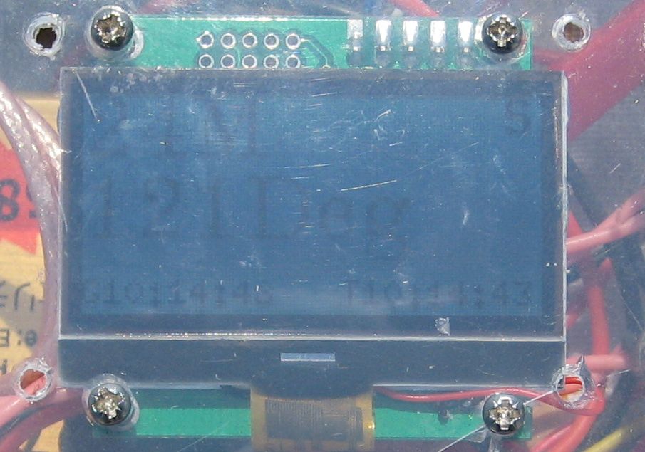
In the small text mode (font size 6) the 5110 can display 6 lines of 14 characters, enough for latitude and longitude of both tracker and receiver.
The Hi-Tech case is clear food container, they are cheap, robust, and easy to work and you don’t have to cut holes for the display. To make it easier to stick stuff down, secure a bit of varnished wood with some bolts in the box base, you can then use sticky Velcro to secure things in place.
The finished receiver is as below, the LEDs on the RFM98 Shield can stay on the PCB, and they are easily seen through the clear case. The switches are on the case top together with the display and are used to change between large display mode, distance and direction only, and small display mode which shows the Latitude and longitude of both the tracker and the receiver.
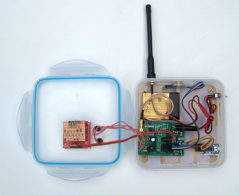
The receiver GPS is just to the right of the antenna connection.
Lost in the City?
One of the worst cases scenarios for using radio telemetry for locating lost stuff, model planes, balloons and dollies, is if the tracker (transmitter) is on the ground in an urban or forested area as the buildings or trees will cause heavy attenuation of the UHF signals.
The tracker, shown above, was PICAXE based using a LoRa RFM98 module and a Ublox Max 8 GPS. This tracker was launched on a Helium filled foil party balloon and was tracked across Europe for around 1000miles. I was able to pick up the 10mW\1042bps LoRa telemetry at up to 269km and the 2mW\98bps LoRa telemetry at up to 244km. The device can put out as much as 50mW, so greater range is clearly feasible.
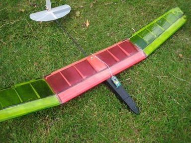
The pictures below show the test tracker on a model plane (Gambler DLG) on the ground in my garden. Note the antenna (1/4wave wire) is very close to the ground, perhaps worst case for a lost model. My models do normally end up lost in trees, but that’s because around here we have a lot of special trees that are magnetic to balsa and plastic. The tracker runs LoRa at 434Mhz and 10mW output power. It has its own GPS with one of the ceramic stick antennas, which is OK most of the time and very light, but you can connect up a separate GPS with integrated active antenna, such as the GlobalTop\Mediatek devices, which will give a faster initial signal acquisition.
Two antenna options were tested with the receiver, the normal portable and not very effective, rubber duck style antenna and a magnetic mount antenna (4dB gain) on a car roof. It’s hard to describe the detail of the type of terrain used in these tests, so I have included some pictures.
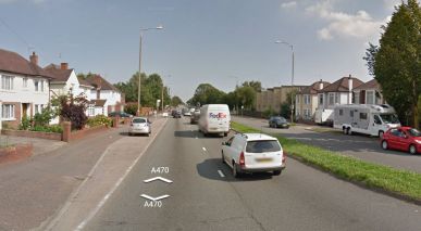
I went walking up the street to see how far away the tracker transmissions (it’s GPS co-ordinates) were received. Reception stopped at 825m, not bad at all, This is the view back to the tracker\plane;

How far away would the tracker be received by the ‘chase’ car with its mag mount antenna? I left the tracker on the plane as before and drove to work, I had the tracker signal several times at 1.5km away on the way out to work, and again when I returned home that evening, this is the view back to the tracker;
I last got the signal from the tracker when I was 2.2km away, considering the terrain this is quite remarkable.
Very Lost in the City?
So what happens if you only have a vague idea where your lost tracker is ?
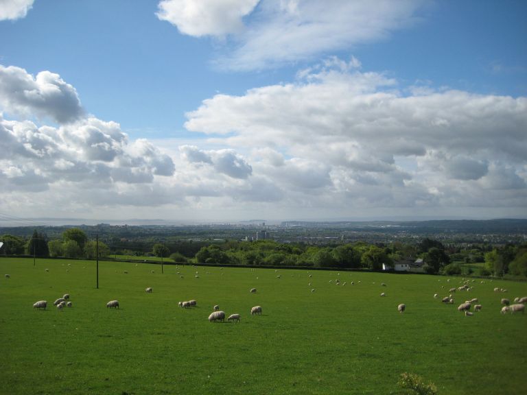
The picture above is the view of Cardiff from the North, the tracker is again on the ground in my garden somewhere in the middle. Note the two Islands in picture centre, they are Flatholm and Steepholm where some guy called Marconi also did some range testing in 1897.
Interestingly I could not hear the audio tones the tracker was putting out on my UHF hand-held as there was a very strong buzz (interference) on 434.400Mhz coming from the city! So a simple tone beacon tracker, which you would normally expect to work quite well over that range, was useless.
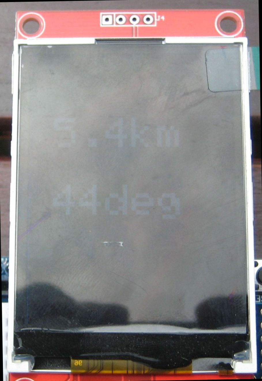
I picked up the telemetry from the tracker which the receiver said was 4.5km away using only a rubber duck style antenna on the receiver. This test demonstrates not only the sensitivity of LoRa but that it has a high resistance to interference.