Semtech LoRa® Transceivers a KISS approach to Long Range Data Telemetry
Introducing LoRa
In 2013 Semtech released a new RF IC transceiver designed to be used for the industrial scientific and medical (ISM) market, this was the SX1278 and its variants. These transceivers use a proprietary spread spectrum transmission method they called LoRa; short for Long Range. The claim is the devices are capable of receiving signals at below noise level, the limit being -20dB signal to noise ratio (SNR) at a spreading factor of 12. Frequency shift keying (FSK) transceivers such as the RFM22B need a positive SNR of somewhere between +5 to +10db, so potentially the LoRa device can operate with signals that are up to 30dB weaker than those required by the RFM22B and similar FSK devices.
A 30dB improvement in link margin is an approximate range gain of 30 times so the LoRa devices do look just a little bit promising.
The Semtech SX1278 was incorporated in 2014 in two ready to use UHF\434Mhz modules, the Dorji DRF1278F and the Hope RFM98. This report will investigate the performance of these 434Mhz modules.
Experiments with FSK Transceivers
The Hope RFM22B is an example of a low cost FSK transceiver module that was able to provide a communications link for two low Earth orbit amateur satellites, $50SAT and T-LogoQube. The results produced by the T-LogoQube team being particularly impressive as they demonstrated 2 way communications at up to 2,700km with only 100mW output from the satellite.
Such long distance operation of the FSK transceiver modules required the use of a 50W power amplifier for uplink, a low noise amplifier (LNA) for the downlink and an antenna farm of accurately tracked twin 20dB long yagi arrays to follow the satellites path across the sky. Whilst it worked well the equipment is not simple to set up or operate and is expensive.
The $50SAT team, Howie DeFelice, Michael Kirkhart and Stuart Robinson were able to receive the data telemetry at up to 1200km from $50SAT using hand held antennas and low noise amplifiers.
These ISM band transceivers have up to 100mW output although for license exempt ISM use the limit is normally 10mW. For amateur band applications amplifying the power from these simple 434Mhz transmitters is not that difficult. Mitsubishi do a series of UHF power amplifiers that will take a low input power, 25mW or less, and boost it to as much as 60W.
FSK transceiver modules do need a good LNA in front of the receiver for long distance operation, the LNA adding around 12dB of useful signal gain, which is a range improvement of about 4. To use the LNA and power amplifier together you need either separate antennas for TX and RX, (not very convenient) or sequencing and switching of the single antenna between RX and TX modes. This is all possible of course, but is not simple or cheap to set-up.
The $50SAT satellite side installation was an example of a ‘keep it simple’ system, but this was clearly not the case for the ground station set-up. To reduce complexity and cost we need to eliminate the LNA, power amplifier, output filters, sequencer, antenna farm, rotators and connect our humble transceiver module direct to a single simple antenna, but how far are we going to get at only 10mW or 100mW with FSK transceivers?
Assuming ¼ wave antennas at both ends of a link an FSK transceiver will at 1000bps go around 12km at 10mW and 40km at 100mW. 12km for 10mW or 40km for 100mW is good, but it does not allow for a low complexity set-up for satellites or high altitude balloon use where ranges of 200 to 1000km may be needed.
FSK transceiver modules can be used for long range reception however, by using a low cost LNA and or high gain antennas. In mid 2014 I launched a Pico balloon using an RFM22B as the transmitter. With a Diamond X50N vertical antenna (5dB low horizon gain) and £50 LNA kit I received 1000bps telemetry from the balloon tracker with 10mW output at 174km. Since balloons don’t move around the sky much, a long yagi could be set-up on a mast or tripod and it would not be difficult to manually point it towards the balloon. However, the uplink would be troublesome, since 10mW into the yagi would exceed the effective radiated power (ERP) limit of 10mW.
Although this is a report about the LoRa transceivers, I do make many references to the RFM22B. I did a great deal of testing with this module for the $50SAT project and I can therefore make direct comparisons, by using the same tests in the same locations, between an FSK transceiver and a LoRa one.
Testing LoRa
The first tests I carried out on the LoRa devices were on the Dorji DRF1278F module. There was some working program code available for Arduino, so I connected the DRF1278F to a 3.3V modified Arduino UNO. The tests described were carried out at UHF frequencies at around 434Mhz.
The Long Walk.
I don’t, unfortunately, have the benefit of a laboratory full of test equipment or a nearby large underground cavern far from sources of radio interference and noise, so I make do with the environment around me in South Wales instead.
In practice these transceivers will be used in real world situations, so it seems appropriate to test them in similar situations. A good laboratory performance is one thing, but a ground based receiver will probably be in the middle of an urban or industrial area and have to cope with all the associated RF Noise, so why not test it there?.
The Arduino program code was changed to put out a data transmission at approximately 60bps at 10mW, the low data rate chosen to maximise range. An RFM22B was then programmed to send data at 1000bps at the same power. The data rates were not the same, but testing for $50SAT showed that the RFM22B performance did not improve much at data rates below 1000bps anyway.
Both transmitters were mounted in similar tin boxes from the local £1 shop, with a 20dB attenuator in-line with the transmit antenna. The actual radiated power from the antenna was therefore only 100uW. Each transmitter had a matching receiver that made an easily heard beep whenever a packet was received
Comparing the performance of the LoRa device to the RFM22B meant that if a dB performance relationship could be established between the two devices, we could extrapolate from the known performance results of the RFM22Bs that have been in low Earth orbit and then form a view as to the distance performance of the LoRa device in the same situation.
At the beginning of September 2014 I was staying in the South Wales seaside resort of Tenby and the beach provided a good testing range mostly free from obstructions (at low tide) see pictures below.
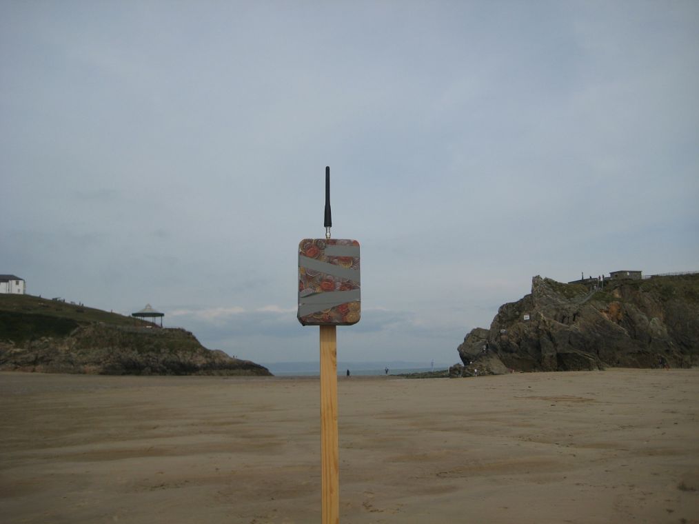
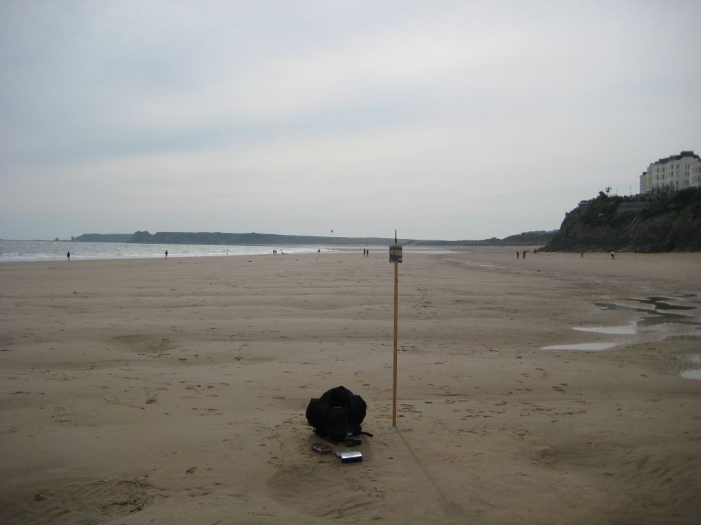
The testing principle here is simple, walk away from the transmitter until the beeps stop. The distance difference can then be converted into a dB performance ratio.
With the RFM22Bs the reception stopped at approx. 100M.
Rather a longer walk was needed with the LoRa devices, approx. 1km, so 10 times further. 10 times further represents a link improvement from the LoRa device of 20dB over the RFM22B.
I was very surprised by these results and impressed, but a method was required to allow more accurate comparisons between the LoRa device and the RFM22B without the need to walk very long distances.
Descending Power Testing
With both the LoRa Device and the RFM22B you can vary the output power of transmissions. If you set up the devices so that the transmitter sends a series of descending power packets, with the power level sent as part of the packet, the receiver can record at which power level reception stops.
First set up the link with the transmitter and receiver some distance apart. Set up the transmitter and receiver to a particular data rate and you note that in this case reception stops at 10dBm from the transmitter, i.e. the 11dBm packet is received but the 10dBm and lower power packets are not. You change data rate settings to a lower data rate and note that reception now stops at 5dBm. You can conclude from this that the lower data rate has a 5dB performance benefit over the higher rate. A better performance for the lower data rate would be expected, but you have now quantified the difference and can convert this into a distance improvement. A 5dB link performance improvement would increase distance by 75%.
The typical output of the receiver program is as below;
Powers,16,16,16,15,16,16,16,16,8,2,0,0,0,0,0,0
With 17dBm on the left, and 1dBm per step you can see performance is consistent in this test down to 10dBm, only half the packets received at 9dBm, and only 2 at 8dBm.
I next set-up a LoRa transmitter and a RFM22B transmitter to send out data packets at 1000bps at a location approximately 750M away from my home workshop across an urban area. The transmitters were side by side on a short pole about 1M from the ground, and on separate frequencies of course.
I adjusted the height of the antenna (a QF Helix) on my mast so that I was only getting the most powerful 17dBm packets from the RFM22B, the lower power packets were not being received. I then swapped across to the Dorji DRF1278 receiver, and I was also only getting the most powerful 17dBm packets.
This does not seem to be any improvement, apart from the fact that the antenna on the remote LoRa transmitter was fitted with an in-line 20dB attenuator!!!
The software also turned on the transmitter for a brief period with no modulation and at each power level. When received with a Funcube dongle and SDR# software, this signal appears as a spike on the SDR# display, so you can measure the signals received dB level. In this way I could confirm that the LoRa transmission was indeed 20dB lower than that of the RFM22B.
So in this test, across a typical urban environment, the LoRa device has a link budget gain of around 20dB over the RFM22B at the same data rate, which equates approximately to a range difference of 10 times.
I re-programmed the LoRa device so that it was transmitting at the lower data rate of 100bps. The LoRa reception now stopped a further 10dB lower, the 7dBm packets were now received. Thus the 100bps LoRa transmission has a potential range improvement over the 1kbps RFM22B transmissions of 30dBm (20dBm + 10dBm) this represents an approximate distance improvement of 31 times. So if I needed 17dBm to cover 750M in an urban environment then the lower power of 10dBm\10mW (the ISM limit) would have a range of about 350M, so how far would the LoRa device go? The tests suggest LoRa would manage 3.5km at 1kbps and 11km at 100bps!
The Long Drive
I did the same long range line of sight test that I did for the RFM22B back in 2012, 40km between two hilltops across the Bristol Channel (route 3 on the map below). This original test was for the $50SAT project, some figures for real world performance were needed to do uplink and downlink budget calculations.
Although the distance was ‘only’ 40km it was a fairly long drive to get from Cardiff into position on a hilltop across the Bristol Channel.
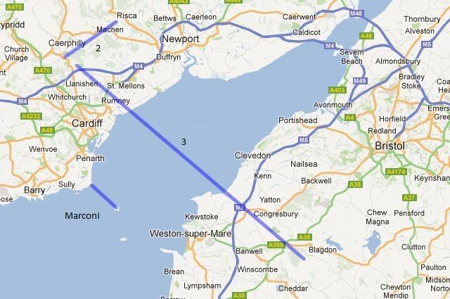
Route ‘Marconi’ on the map is the where the first radio transmission across water took place in 1897, by Mr Marconi, not sure of his call sign.
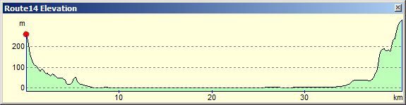
The route chosen had good line of sight and had plenty of altitude in the middle of the route to minimise Fresnel zone effects, see the profile below.
The RFM22B had been sending data at 1000bps in the original $50SAT test. The LoRa device was programmed for 1042bps (Bandwidth of 41.7 kHz, Spreading factor of 8, Coding Rate of 4:5). Antennas were simple 1/4 wave wires at both ends, transmitter and receiver were in tin metal boxes with no real ground plane, as for the previous tests mentioned in this report.
At the receiver end all that was necessary was to listen with a UHF hand held for an audio tone, this indicated the start of the 17dBm to 2dBm sequence and count the beeps, 1dBm less for each beep. The terminal output of the receiver was also saved as a log file for analysis. Reliable packet reception for the RFM22B had needed 20dBm for the 40km, the LoRa device only 3dBm, so a 17dB performance gain.
17dB is a significant improvement!
Following the 40km\2mW LoRa result, Howie DeFelice produced a link budget calculation spreadsheet for the LoRa devices.
One anomaly that was clear from the results of Howie’s link budget calculation was that the signal strength of a 2mW transmitter at 40km calculated as -114dBm.
As 3dBm\2mW was the proven limit of reception, you can conclude that the receiver needed at least -114dBm of signal to reliably operate. However, the Semtech LoRa calculator application claims the sensitivity at the bandwidth and spreading factor used was -131dBm, so where has the missing 17dBm gone?
The sensitivity quoted in the data sheets is probably a figure that cannot be achieved, at least in non-laboratory situations on Earth, since the real life background noise level is so high. I checked and a typical background noise level reported by the SX1278 RSSI register during the 40km test was around -100 to -105dBm. My RF Explorer spectrum analyser reports a similar level. With noise at that level there may be little value to be gained by the LoRa receiver having a sensitivity of up to -148dBm as the data sheet specifies.
Where the LoRa device seems to be is getting it’s real world performance from (it is clearly substantially better than the FSK receiver in the RFM22B) is its ability to receive signals below the noise level. The acceptable signal to noise ratio (SNR) for the spreading factor used in the 40km test (8) is quoted in the Semtech data sheets as -10dB, so the receiver should work if the signal was 10dB below the received noise level. 10dB below a noise level of -100dBm is -110dBm, close to the predicted signal level that 40km\2mw would have produced (-114dBm).
So whilst the receiver predicted sensitivity (of -131dBm) might suggest far greater range than 2mW for 40km gives in reality, it’s the relationship between local noise level and SNR performance that appears to predominate.
I then carried out some shorter range tests using the same descending power test method as above, but with the antenna output fitted with an attenuator in order to cut the distance down. At a spreading factor of 12, the data rate drops to circa 100bps, and signals were received at 10dBm lower, the SNR at this point is reported as -20dB.
So reducing the data rate from 1000bps (used for the 40km test) down to 100bps, does appear to increase link budget by a further 10dB, reducing the data rate to 50bps gives 13dB link gain.
Problems?
There was one issue noted in the initial testing of the hardware that needed further investigation.
I was testing at a bandwidth of 20.8 kHz, Spreading factor of 11, this gives around 100bps and would be a good replacement for the FSK RTTY often used to send tracking information from a high altitude balloon in the UK. In the UK amateur radio license holders cannot transmit from ‘airborne’ devices so we are limited to 10mW ISM stuff.
It appears that there was something happening with the higher power packets at the 17dBm to 14dBm level. In the receiver report below the higher power packets were received but had CRC errors. The weaker packets are received fine.
Powers,0,0,0,2,5,5,5,5,5,5,5,5,5,5,5,5
The packets were well attenuated at the transmitter so it seems unlikely that the transmitter was over driving the LoRa receiver.
The cause of the problem appears to be the same heating that affects the RFM22B\Si4432. The IC package heats up when the transmitter turns on and this alters the oscillator frequency slightly since the oscillator circuit itself heats up as the chip heats up. This shifts the frequency and is very easy to spot when receiving a signal in FSK side-band mode
It may be that just replacing the crystal with a plain oscillator module would be enough to improve the short term heating issue, it would take a while for the TX heating the chip to cause a separate oscillator to heat also. To be fair the data sheet does suggest that the device is susceptible to short term stability issues, so the issue should not have been a surprise.
I decided to measure the frequency drift of the RFM98 when the transmit was turned on. The transmit was turned on from cold (actually room temperature) at approx 434Mhz with a 10mW carrier and the change in frequency measured at intervals. I used a Funcube Dongle to receive the 434Mhz signal in LSB mode, and the FLDIGI software to display the resultant audio tone; this was the resulting drift away from centre frequency at 5 second intervals;
5 – 50Hz
10 – 120Hz
15 – 160Hz
20 – 210Hz
25 – 240Hz
30 – 260Hz
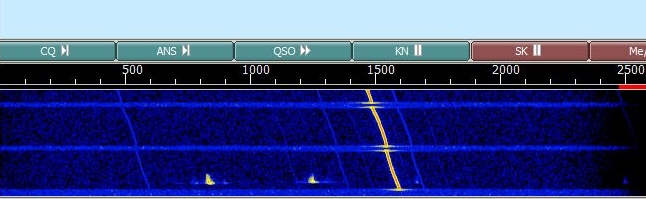
After one minute the drift was down to around 10hz every 5 seconds. It looks like this on screen, the gaps in carrier are at 5 second intervals, the scale marked 500,1000 etc. is in hertz.
The problem (packets received with CRC errors) did not seem to occur with high data rate (1042bps) packets, but was present on the lower data rate (98bps) packets. It was also noted that the errors did not occur in short packets of 10 bytes or so, but did with longer ones. The problem also seemed worse with lower bandwidth packets.
There would appear to be a limit for the allowable frequency drift from the start of the packet which is a small percentage of the bandwidth. The frequency tolerance is stated at 25% of the bandwidth, so at 41.7khz, that’s 10.4khz and the short term drift apparently causing the problem is nowhere near this, as measured above.
What could be happening is that at the preamble time the receiver locks on to the incoming frequency and decodes appropriately. If the transmitted signal drifts by a small amount (I suspect its in the order of 100hz) the receiver decode fails. So lower bandwidth and lower data rates meaning longer packets would be more susceptible to the problem.
The immediate response is no doubt to suggest that the crystal on the Hope or Dorji modules is replaced with a TCXO or maybe just a plain TXO, so that the oscillator circuit doe not get affected by the TX heating effect. But is such a modification really necessary?
It was pointed out by someone on the UKHAS groups that there is a low data rate optimisation bit that I had omitted to set, and this does indeed reduce the problem significantly, especially at a bandwidth of 40.7khz. However this is a potential issue to be aware of, possibly in satellite applications, where the rate of change of centre frequency during the actual reception of a packet can be significant.
There is also the issue of the differences in frequencies between a pair of modules.
Frequency Offsets
The LoRa devices do not have an automatic frequency control circuit (AFC) as such and if the transmitter and receiver differ in frequency so that they are outside of the frequency tolerance for the bandwidth used, the link just stops working, there is no gradual fall off in performance, it just fails.
The AFC in the RFM22B is very effective, there is very little degradation in performance when transmitter and receiver were offset by up to 10khz, and this meant no correction was needed to cope with the Doppler shift from a satellite in low Earth orbit.
I have several RFM98s and DRF1278Fs here, and the crystals do vary in base frequency. If the modules are programmed with the same frequency settings and bandwidth of 20.8 kHz, two of these modules just don’t communicate, the crystals are far enough apart in base frequency to prevent the link working and at frequency separations that are less than the data sheet would suggest. One module was 2.1khz high the other 1.2khz low (at the same temperature). These crystals were 3.6khz apart, the failure point should have been 5.2khz..
You can of course adjust the programming of the SX1278 to ‘calibrate’ the crystals by making fine adjustments (in 61 Hz steps) to bring the crystals base frequency together.
The SX1278 data sheet specifies the frequency tolerance as +/- 25% of the bandwidth, so the 41.7 kHz bandwidth should have a frequency tolerance of +/- 10.4 kHz, so within the Doppler shift range for a low Earth orbit satellite. Higher bandwidths would improve frequency tolerance further, but the higher bandwidth will introduce more noise into the receiver, and reduce sensitivity.
In the UK, if you want to use the ISM bands for continuous duty applications, then the channel use needs to be 25khz or less. At a bandwidth of 20.8khz, its very likely that a TCXO is needed, but at 40.7khz you can manage without, but you do need to keep the on-air time under 10%, which is not a problem for many applications.
As my quest was to keep the long distance link set-up as simple as possible, I decided to stick to a bandwidth of 40.7khz, as it appeared retro fitting a TCXO to the modules would not be required.
So what does this initial testing tell us?
It’s unclear if the LoRa device is intended for long duty cycle operation of 20dBm (100mW) but it is at 17dBm (50mW). So based on the above tests what sort of range could we expect with the LoRa devices running at 50mW, with just simple ¼ wires as antennas?
Estimated range at 1000bps, 50mW = 200km Estimated range at 100bps, 50mW = 633km
The antennas used in the tests above were fairly crude and without an effective ground plane, so it would be reasonable to assume that actual distance, ground to satellite (or balloon) achieved would be even further. This did prove to be the case as a subsequent test revealed, see later in this report.
Also note that an easy build DIY vertical gain antenna, such as a Slim Jim, at the ground station would extend the 633km to close to 1000km.
This report has concentrated on the performance of the LoRa devices without any additional amplifiers in line with the keep it simple approach. The LoRa devices are easy to program for higher data rates which could possibly be utilised if the ground station has better equipment, such as low noise amplifiers and high gain and\or tracking antennas. However the addition of such equipment considerably increases complexity and cost, and the initial testing does suggest it is just not needed.
It would be feasible to make a long range communications system adaptive, send simple commands to a LoRa device at a very low data rate (easy to receive and long range) and have the link switch to much higher data rates when you have the antenna systems that have the gain that will allow the higher data rates to work.
Long Range Line of Sight Testing.
Next I considered the problem of very long distance line of sight (LOS) tests. It will be necessary to have one end of the link at fairly high altitude since the curvature of the Earth means that even for high mountain tops a receiver may be below the radio horizon from the transmitter.
A low cost way of performing LOS testing is to build a small GPS balloon tracker that reports its position back to you. These trackers can be launched using 36” foil party balloons filled with helium. If weighted correctly they will rise to around 6000M to 8000M and float along at that altitude
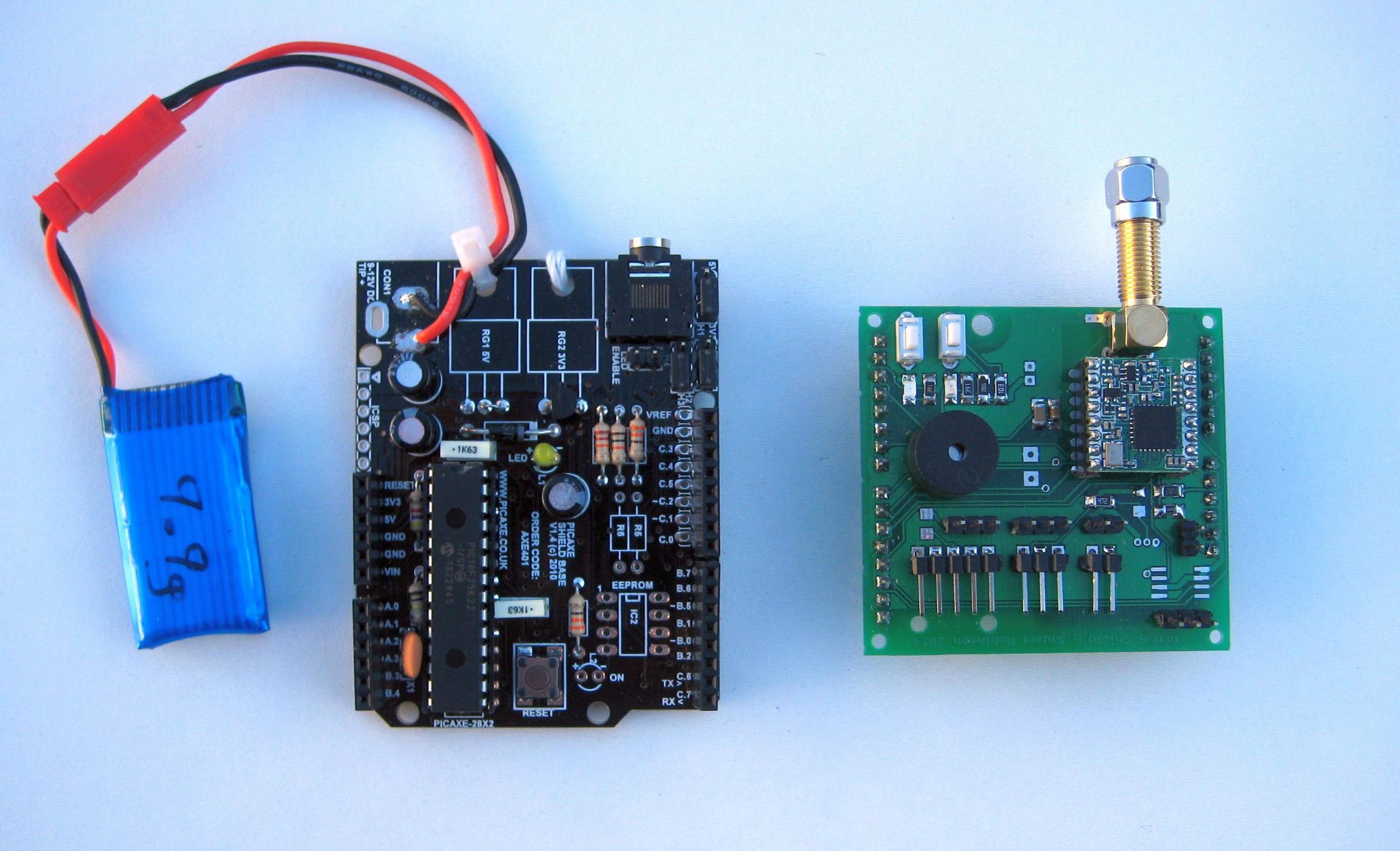
I first produced an Arduino Shield for the RFM98 LoRa device. The shield was designed primarily to allow easy development of the LoRa GPS tracker software, but it can be used as a tracker transmitter in its own right and is also intended to act as the LoRa base station receiver.
This shield is currently running under PICAXE code on the appropriate PICAXE shield base, but the same shield (see pictures below) should work with an Arduino UNO (that’s been converted to 3.3V use) as well.
The balloon would need a small tracker, under 20g including battery, so I designed HABAXE2, see bellow;
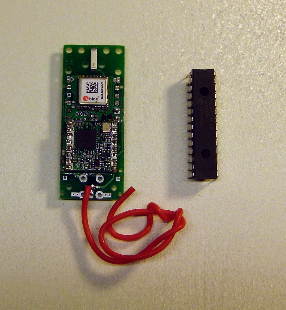
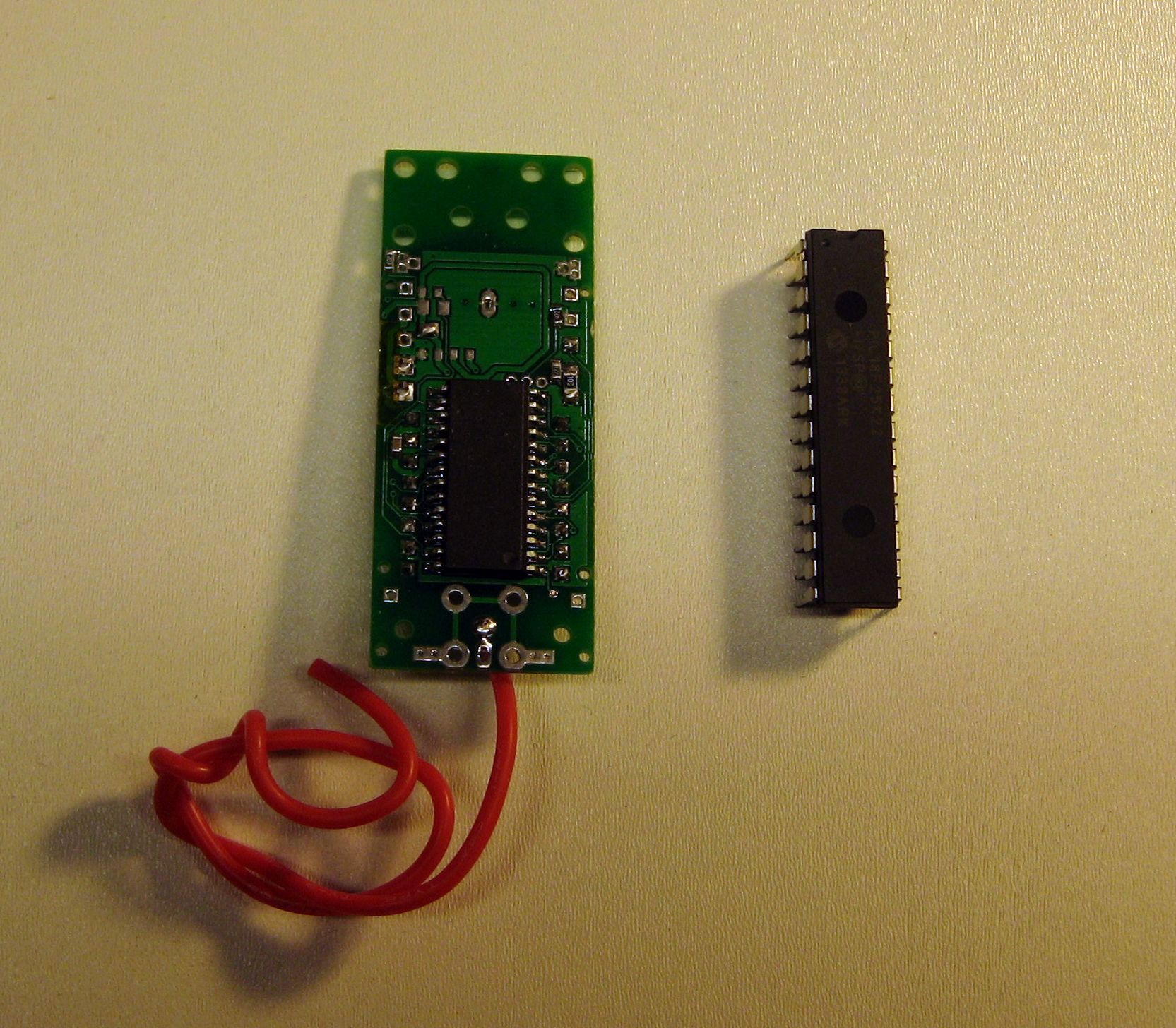
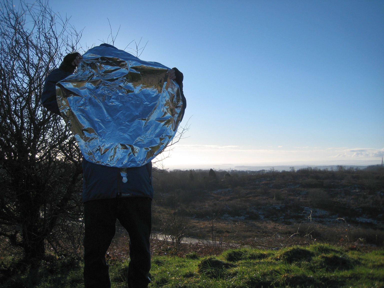
HABAXE2 used a PICAXE 28X2 and the Hope RFM98 radio transceiver. This Pico balloon tracker weighed around 16g with a 10g 380mahr Lithium Polymer battery and was attached to the 36” foil party balloon, filled with helium and adjusted for 2g of free lift, see picture below.
The supplier I use for my PCBs, including the one that has now been in low Earth orbit for 14 months and still working, charges $14 for 10 boards up to 50x50mm including worldwide postage.
The foil balloons are made by Qualatex. The headland in the background on the horizon is Lavernock point and behind it almost obscured by early morning mist is Flatholm island, the site of Marconi’s first transmission across water in 1897.
The RFM98 radio transceiver was sending the UKHAS compatible tracker payload as 100baud FSK RTTY and the same data as LoRa digital telemetry. The antenna was a vertical ¼ wire with 4 x ¼ radials, at 434Mhz.
Radio amateurs would be listening in for the 100baud FSK RTTY signals from the Balloon, unfortunately there are not many LoRa listening stations. Software on their PCs translates the signals and then posts the information via the internet in real time to the central Habitat\Spacenear tracking system. This displays the balloons position and other information in the data payload such as battery voltages and temperature.
One objective of this first flight of HABAXE2 was to see if the RFM98 device could be used for HAB tracking using the LoRa digital telemetry. To this end the ground station receiver was set-up to receive the LoRa tracking data (position) from the balloon and convert it back into NMEA GPS sentences. This was then fed back into a PC via a serial connection so that a mapping application could display the track of the balloon on the local PC screen. I could therefore self track the balloon, but would obviously loose its location once I could no longer receive the LoRa at my location. This concept was also tested using the portable LoRa receiver described elsewhere, that was connected to a small netbook PC and I tracked the first 30 minutes of the flight on a map screen, no Internet connection was needed. I had already established in the earlier tests that the LoRa telemetry at 1042bps could cover 40km line of sight (LOS) with only 3dBm\2mW and a simple ¼ wave wires with no radials, so it was clear that more then 100km was expected at the full 10mW and a better matched antenna.
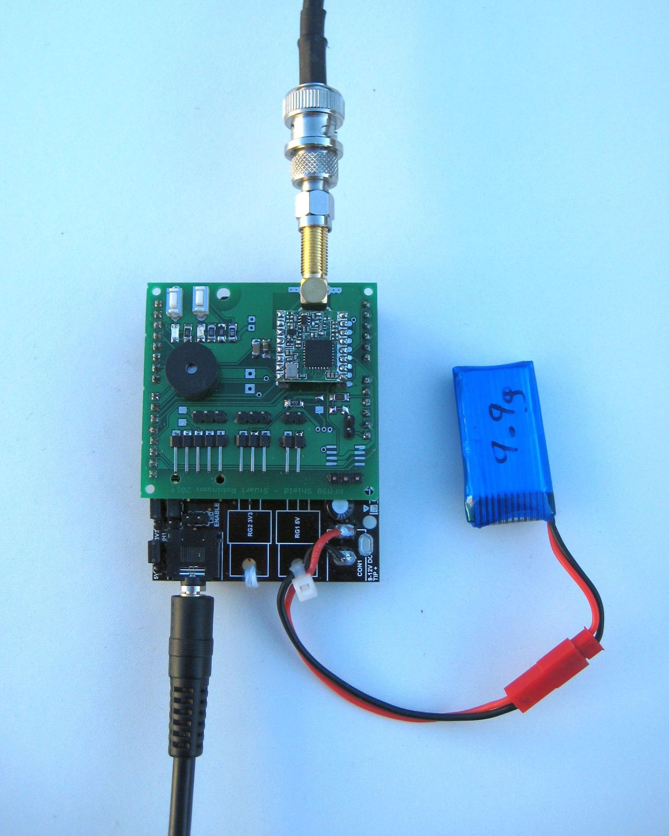
Part of my overall objective was making a LoRa base station that was as simple as possible and to also build a portable receiver. A simple PCB was developed using DIP PICAXE 28X2, this was used both as a base station receiver and for a portable receiver (described in more detail later).
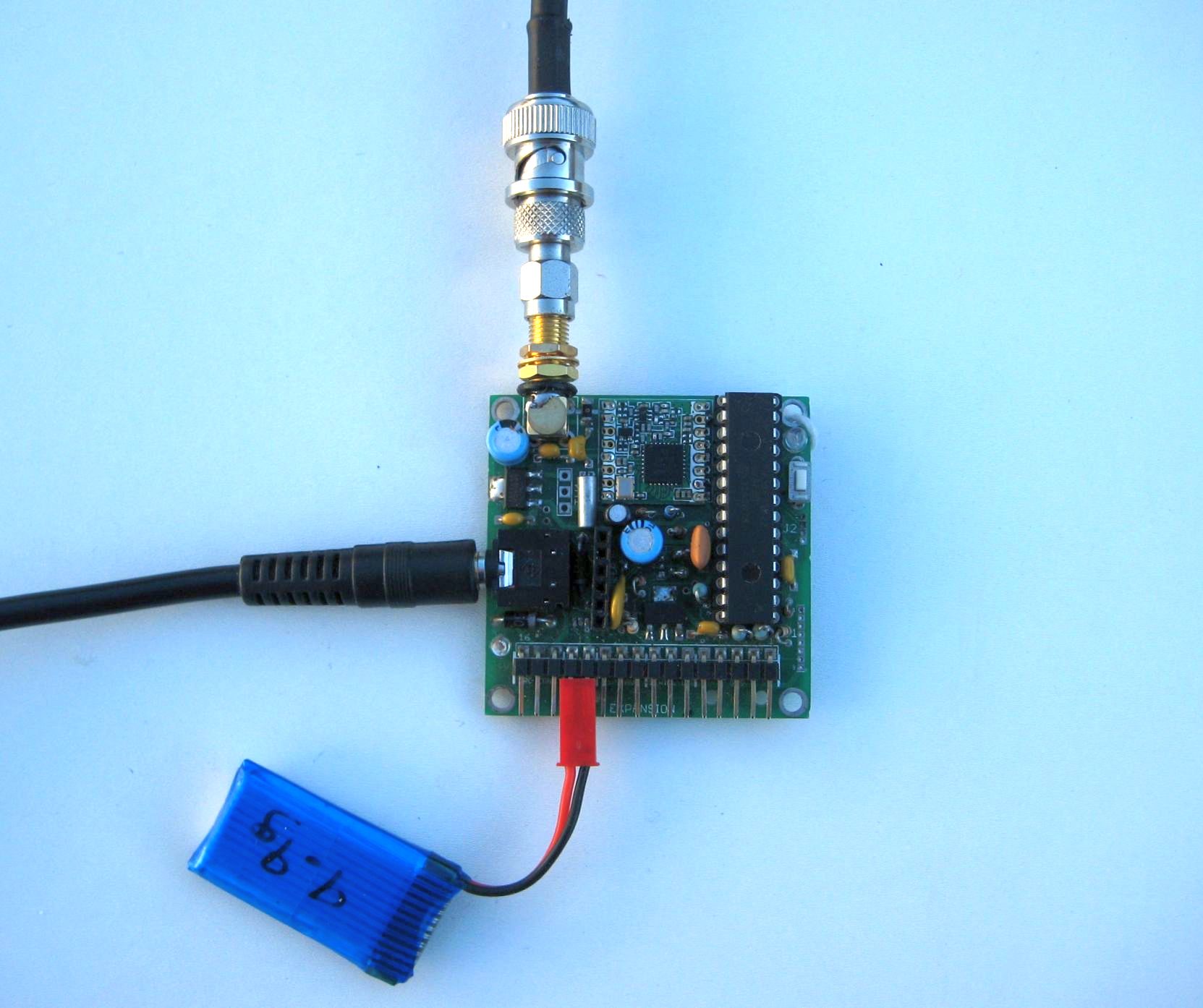
The base station antenna I used was an omni Diamond X50N co-linear, on a mast attached to my shed (I live in the middle of a city). The antenna has a forward gain close to the horizon of around 5dB, similar to magnetic mount antennas for cars.
That is all there is to the receiver hardware and it will run for 12 hours or more from a single Lithium Ion camera\phone battery.
The balloon was launched early one Sunday morning and I retired to the local Café for breakfast, listening for the tracker on the portable receiver I had built.
All looked OK, tracker battery, GPS and the balloon climbing. The track was curling round to the South and East as predicted by the CUSF flight predictor so after finishing breakfast I went home to track from there. The balloon climbed to about 8000M and continued to float along at that altitude.
One of my objectives was to ensure the tracking could be carried out in unattended mode so at home I had left the LoRa base station receiver running. This receiver was set to receive the LoRa tracker packet and upload it into HABITAT with an AFSK RTTY transmission picked up by my Funcube dongle. The first packet was received whilst I was still in the Café 5 miles away and it went into HABITAT OK;
$$HABAXE2,127,09:37:05,51.5372,-3.2062,87,62,357,0,0,0,6,4110,13,Y,0*079A
The payload starts with the station identifier (HABAXE2) then continues with the sequence number of the transmission (127) the GPS time, Latitude, Longitude, Altitude, speed, track, some internal parameters, the battery voltage (4110mV) etc.
A two way command uplink capability was implemented for HABAXE2, the tracker would listen for incoming commands (as LoRa telemetry) for approx 5 seconds just after sending the FSK RTTY. These commands could be used to make the tracker perform various actions, such as warm reset, send RAM variable information or flags for remote diagnostics, send particular NMEA sentences or send a series of descending power packets at a particular set of LoRa modem parameters.
It’s the ability to send descending power packets that would form the basis of the LoRa capability tests, this test method was described earlier. If you commanded the tracker to send a sequence of packets from 10dBm down to 2dBm, with a particular set of LoRa modem parameters and flipped the base station across to listen with the same set of LoRa parameters, you could measure the effectiveness (and hence distance capability) of the particular mode.
The SX1278 needs very few register changes for different LoRa modes and assuming that explicit header mode and CRC mode were on, the payload which is the command to be sent to the remote tracker, possibly hundreds of km away to make it reply with a set of test packets only needed to contain these bytes;
RegModemConfig1, RegModemConfig2, RegModemConfig3, startdBm, endBm, iterations.
The actual payload for ever packet was preceded by 3 bytes, the packet type (telling the receiver what to do or how to act on the data) the destination station (0-255) and the source station (0 – 254). A destination of 255 was assumed to be a broadcast, so 255 stations could potentially share the same channel.
On receipt of this test request, packet type 43, the remote tracker would recognise it, program the LoRa modem accordingly and reply with a sequence of packets starting at a particular dBm power and ending at a particular dBm power and do this is a number of times (iterations).
The ground station would (on receipt of an acknowledge packet from the tracker) flip across to the new LoRa settings and listen for the replies. The reply packets (packet type 44) would be seen by the ground station and would extract from the packet payload the power level used for transmitting the packet. Part of the packet type 44 payload was the power level used. The ground station would display the power level on a serial terminal screen together with received SNR and RSSI information for later analysis. So when the packets stopped coming in, you knew the limit of reception for those LoRa settings, and could extrapolate upwards to what distance could be expected at the 10dBm\10mW ISM limit or the full 17dBm\50mW for other applications.
Thus for one test, I used the higher data rates, bandwidth of 500Khz (BW500Khz) spreading factor 7 (SF7) and a coding rate of 4:8 (CR4:8) that gave an equivalent data rate of 13.7kbps according to the LoRa calculator. At my base station I received the above packets down to 7dBm at 105km, the distance was taken from the location in the previous tracker payload. Thus you could conclude that this 13.7kbps rate would have a range at 10mW of 150km.
The main tracker payload and 2 way communications were being done at BW40.7Khz, SF8 and CR4:5, approx 1042bps, so this would have been expected to operate over a longer distance than the 13.7kbps telemetry.
Putting a good LNA in the receiver side does help with the low spreading factor rates (lower allowable signal to noise Ratio {SNR}) and in this case my masthead LNA allowed me to receive the same 13.7kbps packets at 2dBm, so an 8dBm margin. Thus at 10dBm it would be reasonable to assume a potential range improvement of 2.5 or a distance of around 250km for the 13.7kbps rate.
The main tracker payload (same as the FSK RTTY) was being sent out as LoRa at the 1042bps rate. The last time this main tracker payload was received error free was at a distance of 269km, and note no LNA was used.
Once the high rate 1042bps packets were out of range at ‘only’ 269km I could not test communications any further since the command link was also set at 1042bps. However at 242km I did command HABAXE2 to send a series of 98bps SF12 packets which were received error free down to 2dBm\3mW. Extrapolating the 2dBm upwards to 10mw (UK limit) would represent a UK legal range @ 10mW of 611km, which is the radio horizon at an altitude of circa 22km.
There was a problem with the low data rate 98bps packets, due to an omission on my part that the low data rate optimisation bit was not set for the trackers LoRa modem. This did not affect the shorter test packets but the short tracker payload of 22bytes being sent at @ 98bps was being received with CRC errors. For anyone listening out for the 98bps during the flight, if you received it (but got a CRC error) bear in mind that the TX power from HABAXE2 had been set to 2mW only. So at whatever range you received the 98bps during the HABAXE2 flight, it would likely have been received at approx 2.5 times that range assuming the tracker had been set up correctly with the low data rate optimisation bit set and the full 10mW had been used.
I also implemented and tested a method of adjusting the base station frequency to match the tracker frequency which could drift due to the cold. This was done by switching the base station antenna to the Funcube\SDR# and using the SDR# screens frequency cursor to mark the incoming FSK RTTY idle frequency. With the antenna then switched back to the LoRa receiver a menu option allowed a small marker carrier to be sent out which could be shifted up and down via the keyboard to match the frequency cursor on the SDR# screen. This method worked and would be required to allow the LoRa transmissions below 41.7khz to be used with the standard RFM98.
Flight Details
The balloon was launched around 09:30 on the 4th January 2015, from Caerphilly Common, 51.5621N 3.2228W. It was last heard of at Latitude 44.1618N, Longitude 4.3205E at an altitude of 8032M, having travelled just over 1000km.
Due to an error the temperature was being displayed at an offset of minus 128C, so the last recorded temperature was actually minus 36C.
This is the track as displayed on the Spacenear\Habitat system;
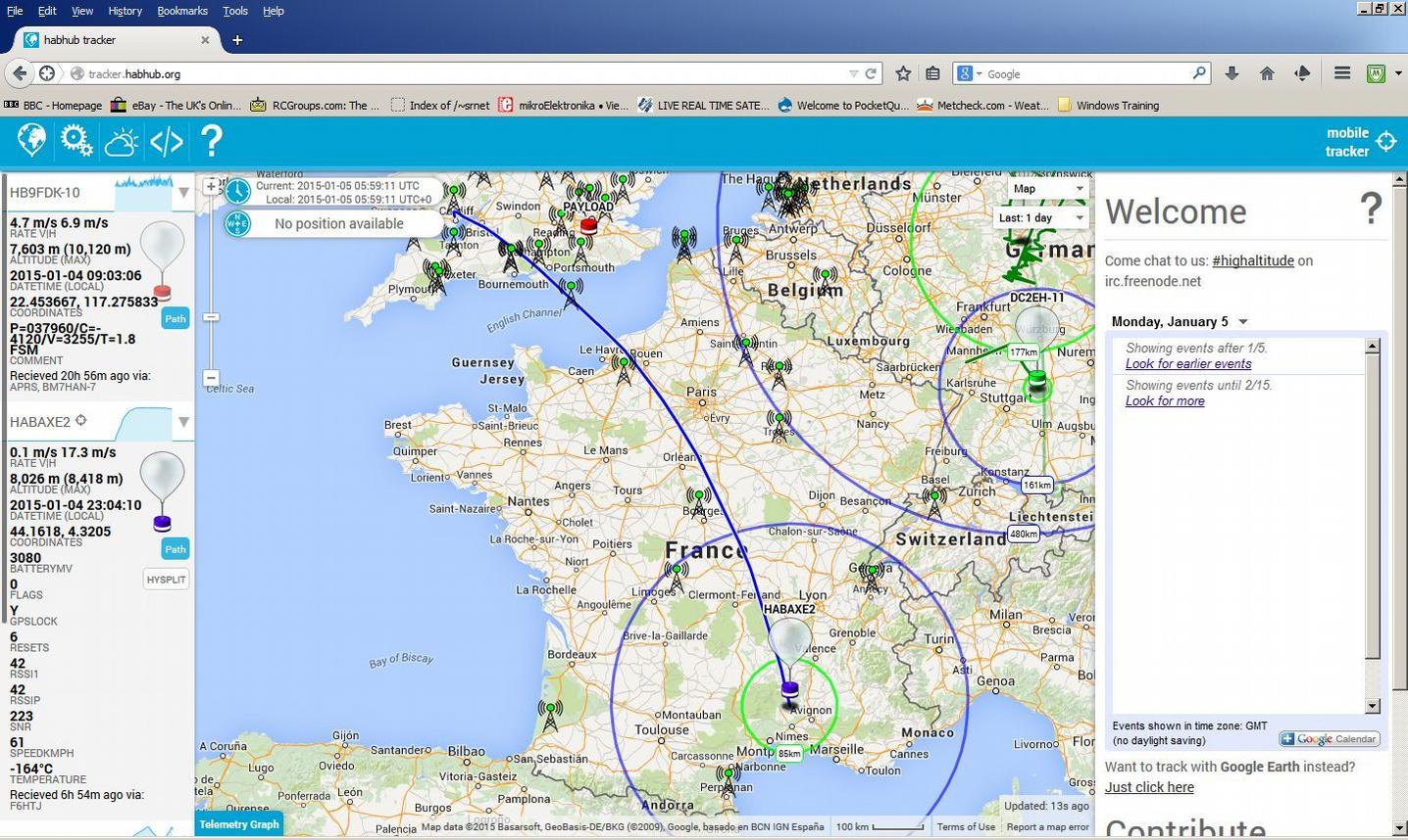
These days 1000km for a Pico balloon is not very far at all, at the end of 2014 one Pico balloon completed 6 times around the Earth!
HABAXE2 had no solar panels fitted, so it was designed to last only 24 hours or so.
World record LoRa link
According to a very very senior LoRa designer at Semtech the establishing of a two way link at 242km used for the testing described above was; “I am glad to tell you that you currently own the world absolute record for a LoRa link”.
Portable LoRa Receiver
One advantage of using telemetry to track high altitude balloons (HABs) is that it’s possible to build small battery powered receivers with simple electronics to display location information from the tracker in flight or one that has landed and needs to be found.
High Altitude Balloon trackers in the UK normally use FSK RTTY which does have very long range capability, hundreds of km. Whilst this can be received with portable equipment, the minimum set-up is probably a reasonably powerful notebook PC and a Funcube dongle which needs constant attention to tuning due to transmitter frequency drift.
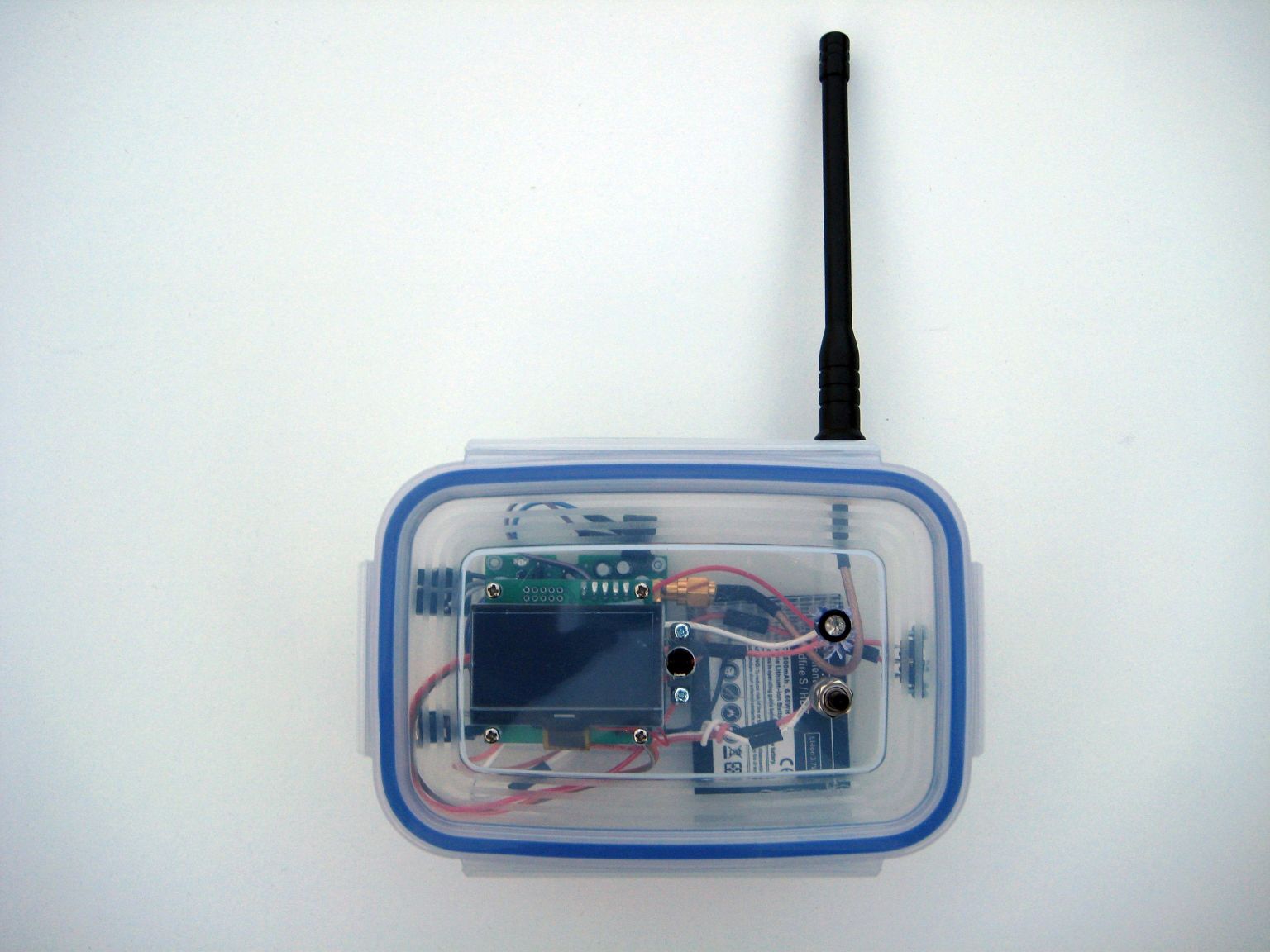
In comparison a telemetry receiver can be as simple as a RFM98 based board, with suitable software, running from a single Lithium Ion battery and driving a serial LCD display. Total parts cost around £25. The LCD can display the received tracker information such as Latitude, Longitude, altitude, temperature etc.
I have found the best displays for this type of application to be the small Digole serial 128×64 graphic LCDs. These are low power and some versions will run from supplies that can vary from 3v3 to 5V with no contrast adjustment needed as the supply voltage changes. These serial LCDs require only a single output pin from a micro controller to drive them. The 128×64 displays will show 7 lines of 21 characters at font size 10, there are other font options and graphics too.
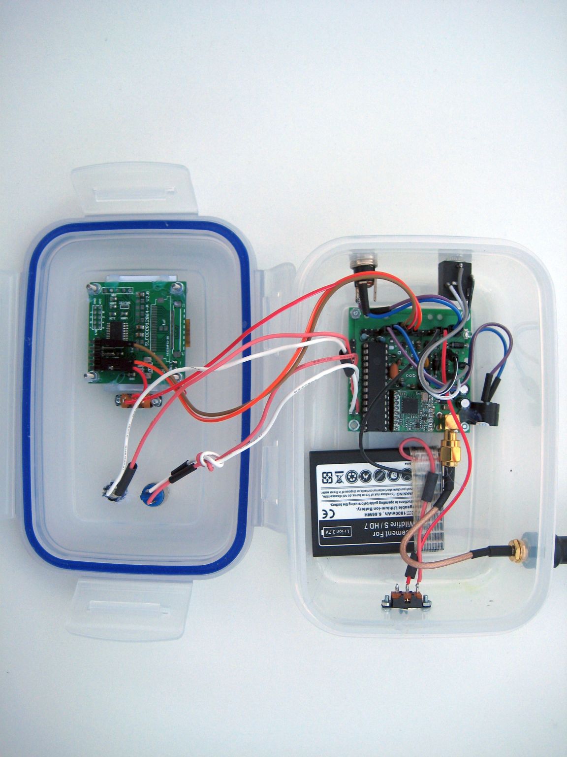
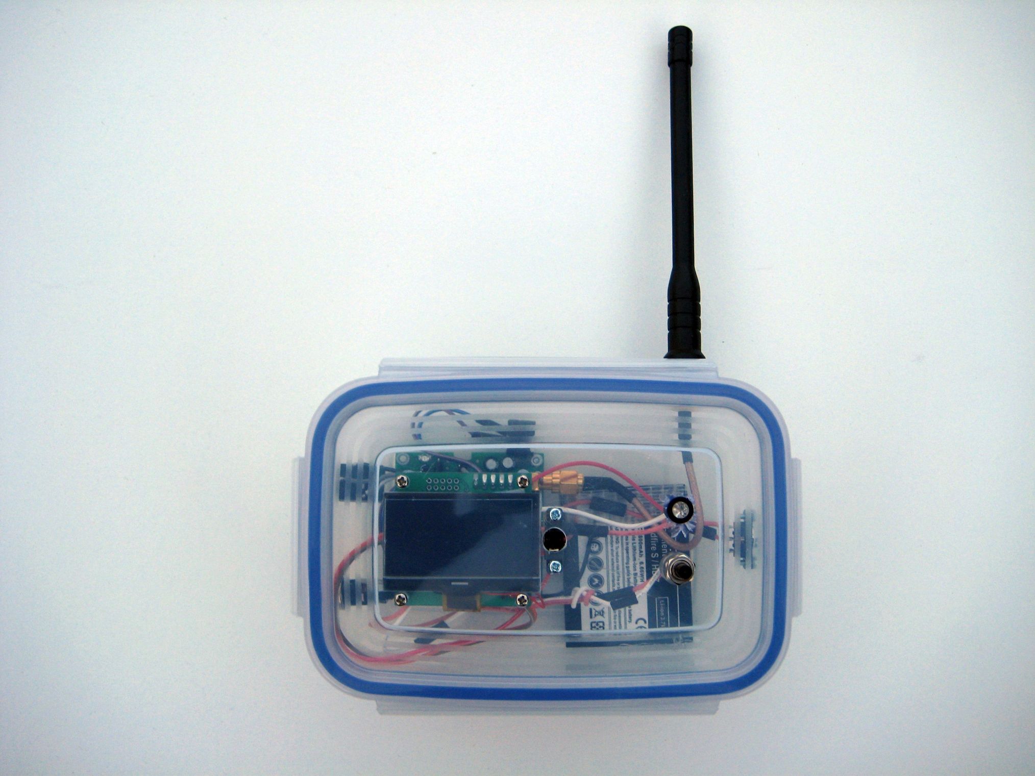
The base station receiver board for the RFM98 and PICAXE 28X2 processor was used for the portable receiver, it is 50mmx50mm. The PCB has connections for the serial LCD, LED, buzzer and switch. The board also incorporates a single cell lithium ion charger IC, so all that’s needed to charge the battery is to connect the external power input to 5V from a USB connection.
The hi-tech case is a clip top food container. These are cheap, robust and easy to work. You don’t even have to cut a hole for the display. For the antenna connection I use a short SMA plug to chassis socket pigtail. A bit of hot melt glue here and there secures the bits in place.
Other uses for a portable telemetry receiver?
One of the worst cases scenarios for receiving the telemetry is if the tracker (transmitter) is on the ground (lost?) in an urban area as the buildings will cause heavy attenuation of the UHF signals.
The RFM22B telemetry in the urban area around my home when a transmitter was on the ground and using a hand-held receiver had a range of around 80m maximum @ 10mW, not a lot of help in locating something ‘lost’.
If the 98bps LoRa telemetry contained the Latitude and Longitude, and assuming this GPS derived location is correct, how far away can it be received on a portable receiver?
Two options were tested, first just the portable receiver with its rubber duck style antenna and the same receiver connected to a magnetic mount 4dB gain vertical antenna on a car.
The LoRa tracker transmitter was placed with the antenna (a 1/4 wave wire) horizontal on the ground in my garden. I then went for a walk up to see how far away the tracker transmissions were received. reception stopped at 825m, not bad at all.
How far away would the tracker be received by a ‘chase’ car with my modest magnetic mount antenna? I left the tracker running and drove to work. I last got the payload from the tracker when I was 2.2km away, a considerable improvement and clearly viable as a simple means of locating a landed but lost balloon, assuming the GPS location being transmitted is valid of course.
For those that believe a PICAXE cannot be used for serious tasks, then think again. PICAXEs are simple to use for beginners and skilled programmers can make them do serious tasks. There are other platforms for these type of applications of course which some may choose to use
What Next?
HABAXE2 used the higher LoRa rate of 1042bps for the command and control link. Since the commands are generally short they can be switched to the lower data rate of 98bps which would provide for a much greater command and control distance. It would then be possible to use a high gain antenna at the base station and thus a high data rate for receiving data and so then reduce the power for the uplink commands and still stay within ISM band ERP limits.
Would a simple modification of the RFM98 modules allow a TCXO to be used? If it were simple then the lower bandwidth of 20.8khz or lower is feasible, which would then allow high duty rate use above 10%. However, if a low duty rate (<10%) is acceptable, then you can use a bandwidth of 41.7khz, where performance seems to be acceptable with an unmodified RFM98.
There is a cut away option for the Pico tracker to be flight tested, instigated by an uplink command. The cut away uses a small LiPo and Nichrome cord to cut the suspension strings (low melting point dyneema), tests on the bench indicate it should work.
For very long distance testing of LoRa it’s going to be necessary to put the LoRa transceiver on a low Earth orbit satellite, very likely a PocketQube like $50SAT. There are some issues with Doppler to be investigated, but if they can be overcome, it’s possible the LoRa will allow telemetry to be received from a low Earth orbit satellite (albeit at a low data rate) with a very low cost portable receiver such as that described above. I don’t think this would have been possible before the clever people at Semtech came up with LoRa. And finally, many thanks to those at UKHAS and HAB enthusiasts in France who assisted in tracking of the HABAXE2 flight.
Stuart Robinson
GW7HPW
January 2015