Testing Antennas Really Is Easy
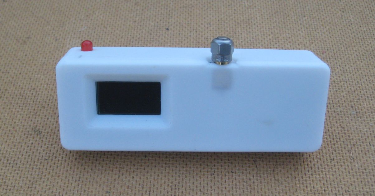
I have previously written an article about testing the real world effectiveness of antennas on LoRa devices but recently it occurred to me that the availability of the small ESP32 LoRa and OLED display boards such as those made by Heltec and Lilygo made it much easier to have small battery powered portable LoRa devices have OLEDs for showing signal reception data such as RSSI and SNR. These small boards often include lithium battery charging capability and have an SMA socket for the antenna making it easy to use a range of different antennas.

Many times LoRa users raise questions or issues about whether particular antennas are good or bad or seek guidance on which is the ‘best’ antenna.
In the RF world its now common to use hand held vector network analysers (VNA), which are low cost these days, to work out how good a match a particular antenna might be for the desired frequency. But a VNA or even a standing wave ratio (SWR) meter does very little to tell you how well the antenna will actually perform in real world situations.
For most portable or point to point applications we tend to use small vertical omni directional antennas. We usually want the antenna to radiate most of its power in a horizontal direction out towards the horizon or to receive signals coming from the horizon. The are circumstances when the transmitter might be at an elevated altitude and the receiver is on the ground, tracking high altitude balloons or satellites for instance but that is not a common use.
A VNA or SWR meter will tell you zilch about the radiating pattern of the antenna. Its entirely possible that a well matched, seemingly good antenna, is radiating most of its power upwards at an angle of 45 degrees or more, which is not much good if the receivers or transmitters are out on the horizon.
Fortunately it really is quite easy to compare antennas and see how they perform when the transmitter and receiver are located in the same horizontal plane. All we need is a flat area, a playing field for instance, and a couple of those nice portable Heltec or Lilygo ESP32 LoRa devices with charged batteries, oh and some suitable software of course.

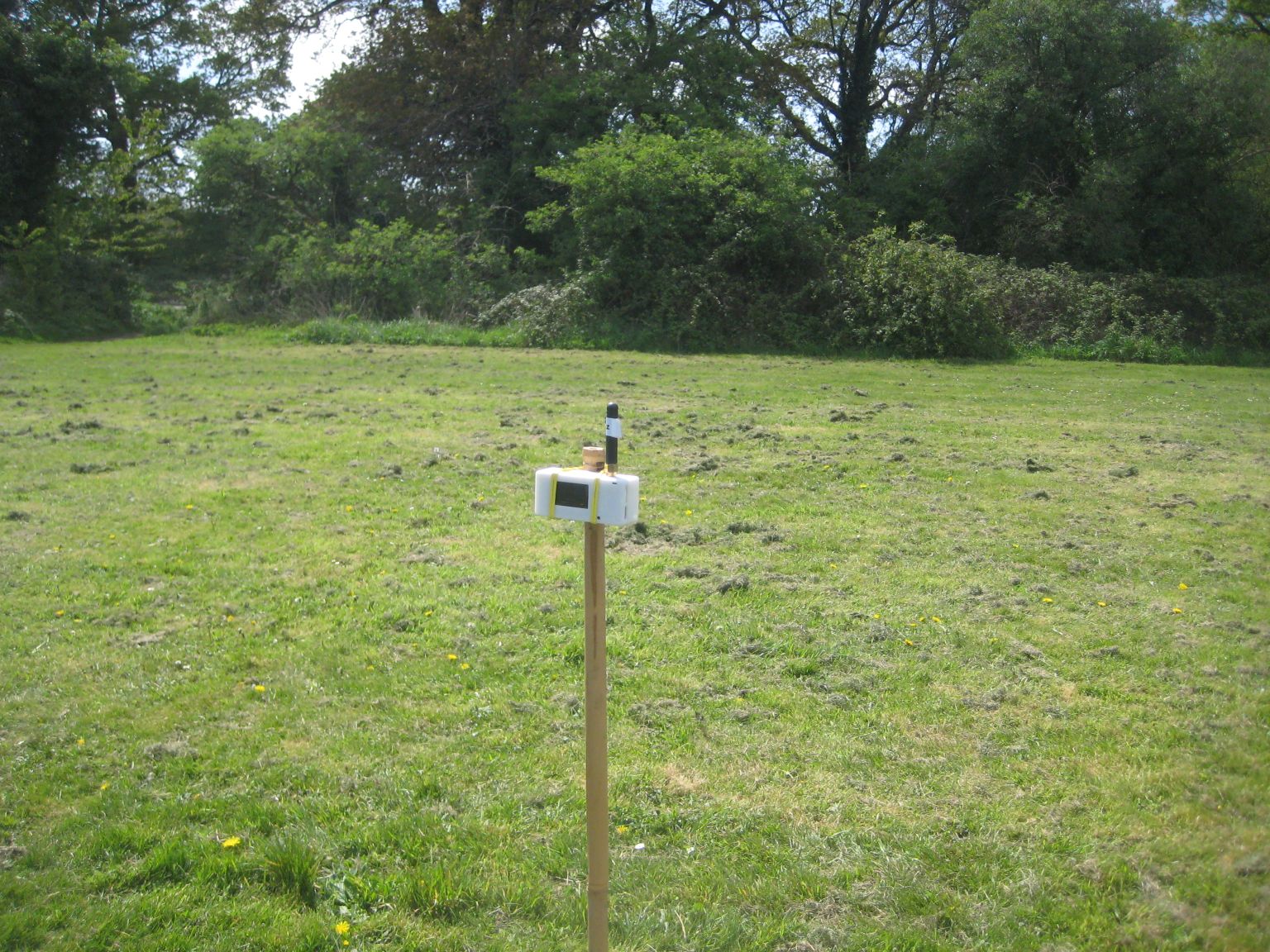
For the transmitter we just need a simple program that transmits a LoRa packet on a regular basis. Short range or fast settings such as spreading factor (SF) 7, bandwidth (BW) 500khz and an RF power of 2dBm will do just fine. Set to transmit maybe one packet a second. Push a shoulder height bamboo pole in the ground and tape the transmitter to the top of the pole.
You will find the transmitter and receiver programs used for these tests here;
Do remember to set the transmit and receive frequencies to match the LoRa module and antennas you are using.
Next program up another of the Heltec or Lilygo LoRa devices with some LoRa receiver software (see above link) that displays the RSSI and SNR of received packets on the OLED display in nice large characters. Switch on the transmitter and take the receiver some distance away from the transmitter, say 50m. Stand sideways on and hold the receiver at shoulder height with an outstretched arm. You need to be sure there is a clear path from the transmitter to the receiver and beyond. Don’t stand facing the transmitter with the receiver in front of you, your body will act as a reflector and can mess up the test.
Lets assume you have fitted the receiver with with antenna A and with the receiver held at arms length you note the RSSI of several of the received packets. Lets say the average is -70dBm. Then turn off the receiver and swap the receivers antenna with another one, antenna B. This time lets imagine the average RSSI is -67dBm.
We can then conclude that antenna B has 3dBm more gain in the direction we want, so its better.
You can now in a couple of minutes test a whole range of antennas and you can quickly work out which is the ‘best’ antenna.
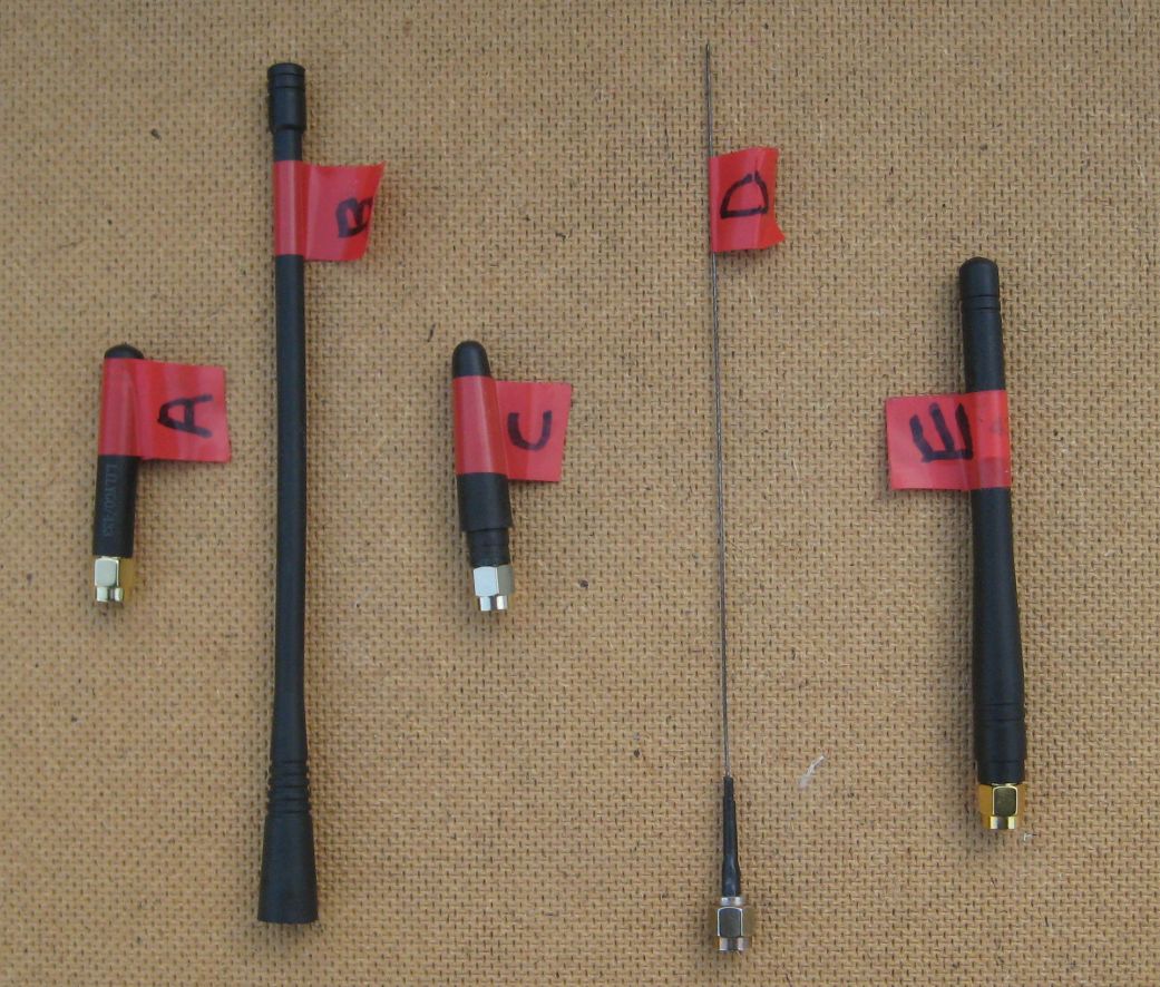
In this practical test the RSSI of received packets for each of the antennas in the picture above was;
Antenna A -76dBm Antenna B -67dBm Antenna C -76dBm Antenna D -66dbm Antenna E -71dBm
So the worst antenna received packets at -76dBm and the best at -66dBm. Also note that the best antenna, the one receiving the strongest signals, was a simple DIY build, a bit of stiff wire 1/4 wavelength long built into an SMA plug.
With a 10dBm difference between best and worst the best antenna should receive signals from 3 times the distance that the worst antenna would be capable of, so a worthwhile improvement.
There is more. If the link advantage by a good choice of antennas is 10dBm for each end, then the total link advantage is 20dBm. So if you had ‘poor’ antennas at transmitter and receiver and then swapped them for good ones, the distance\range the link would work at should increase by a factor of 10. So testing to see which antennas actually do perform the best is worth the effort.
Please appreciate that this very simple test is emulating how the antennas will be used in the real world and we are not relying on VNAs or SWR meters, which could easily mislead us as to which is the ‘best’ antenna.
If you want to simulate weak signal conditions, then you need to substantially reduce the transmitters power level. If you have an SX1262 based Heltec or Lilygo board, that can be set to a power level of -9dBm whilst the SX127X will only normally go down to 2dBm.
There are other ways of reducing the radiated power level, fitting an SMA 50ohm terminator will reduce radiated power by about -30dBm. This in effect moves the ‘distance’ the transmitter is away by about a factor of 30 times.
You can cut also radiated power of a transmitter with an antenna by around -25dBm by putting the Heltec or Lilygo device in a small metal tin.
Have fun testing.