Cycle Alarm Extender
This post describes how to add a LoRa range extender to a vibration disturbance alarm often used to protect cycles. The basic alarm and remote control is low cost and very loud. Of course you should lock a cycle up as well, but there are some impressive portable cutting tools out there so a lock alone is not really enough protection.
A problem with the alarm is that if you go into a shop or a café some distance away for a cup of tea, you may not hear the alarm going off when someone is trying to steal the cycle, especially if in the café the doors are closed or it noisy.
So I thought it would be an idea to have the alarm trigger a LoRa radio transmitter when the alarm made a sound with it’s horn. This LoRa packet would be sent in long distance mode and would be received on a small portable receiver even if your out of earshot of the alarm.
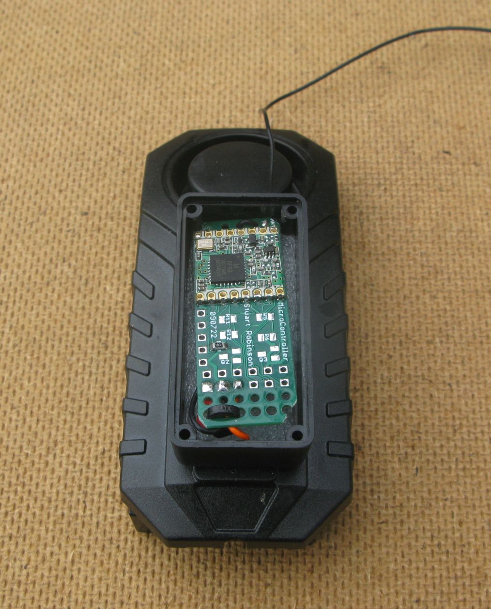
First a small transmitter was needed and a prototype micro controller board is pictured below;
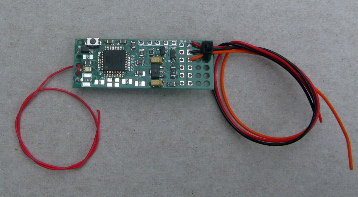
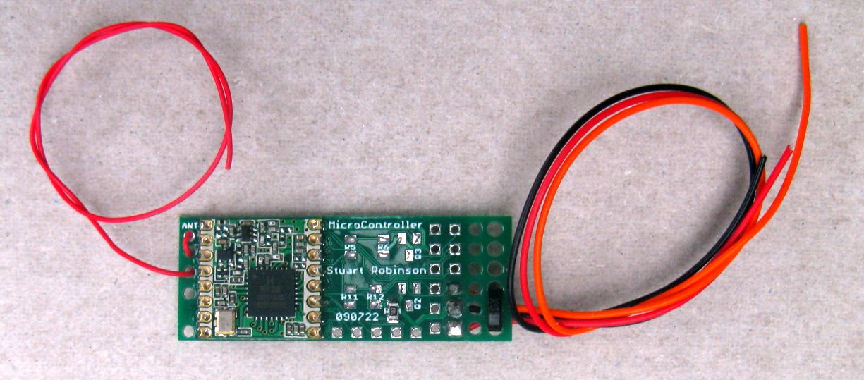
The board uses an ATMega328P processor on one side and an RFM98 LoRa module on the other. The circuit includes components that can be added so that transistors can be used to switch outputs. You can fit resistors to drive external LEDs or read external voltages which could be higher than the devices supply voltage of 3.3V. There is a pin header giving access to I2C devices.
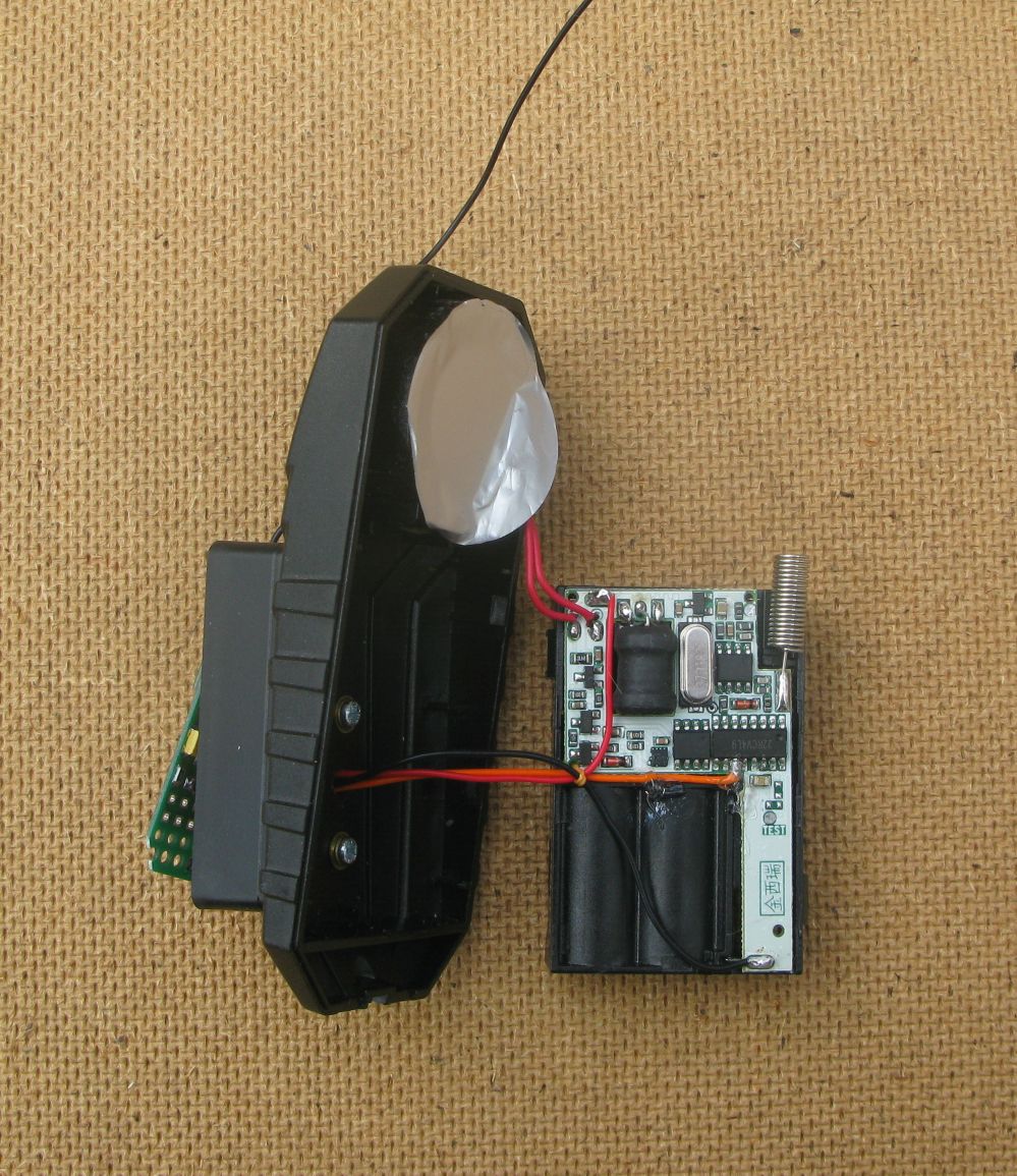
I delved around in the innards of the alarm with an oscilloscope and pin 11 of the IC numbered 22RCV4L9 made a 3.3V pulse train when the horn made a sound. You can see the pin below, it has the orange wire soldered on which in turn is connected to the micro controller.
Its possible there are other versions of the circuit board for these alarms, so you may need to explore a different layout with a scope.
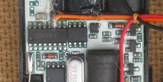
This pin on the 22RCV4L9 is used to wake up the micro controller from deep sleep and then send the long distance LoRa packet. The alarm itself is powered by 3 x AAA Alkaline batteries. The micro controller is powered from the same batteries and the micro controllers voltage regulator will provide the processor and LoRa device with the required 3.3V. The micro controller sleep current should be around 2uA so the 6-9 month battery life of the alarm should not be affected.
This is the schematic of the prototype micro controller, its a redacted diagram to show only the parts used for the alarm application;
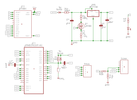
Only 3 wires should be needed to connect the micro controller to the alarm, 2 for power and one to read the alarm output. You can see the three wires, black,red and orange that connect the micro controller to the alarm in the picture below. The orange wire, which is sensing the alarm sounding, is fixed in place with some gel type superglue.
I found a small project box which would fit the micro controller, a CamdenBoss RX2KL05/S-1, I got 5 boxes for £5.70 on eBay. This small box (49 x 24 x 16mm) could be secured to the front of the alarm, with the 3 wires coming out underneath the alarms battery and circuit board block.
This is the micro controller in its small box fixed to the front of the alarm;
I tested the actual deep sleep current of the micro controller and LoRa device, it measured at 2.6uA with a 4.5V battery attached. The processor running current was about 3mA to 6mA. With LoRa transmit set at 10dBm\10mW, the current consumption was 39mA and then 15mA in listening mode waiting for the acknowledge from the receiver.
Total alarm power consumption when off was 11uA with pulses every couple seconds up to 350uA. presumably these pulse are the radio turning on to listen for the remote.
Alarm receiver
You could use just about any LoRa receiver to pick up the warning packets from the alarm micro controller but I decided to make a basic small receiver using another of the micro controller boards as used for the transmitter.
Micro controller board as receiver
Using the the micro controller board described above you can build a small receiver that will notify you of an alarm condition. For the battery 2 x AAA alkalines were used. A buzzer was needed, one of those small 5V ones will work OK at 3V. There was an external LED added which would flash every couple of seconds to indicate that the receiver was working.
I found a small project box on eBay, a ‘60x36x25mm Waterproof Plastic Electric Project Junction Box’. I got 5 of the boxes for £4.60.
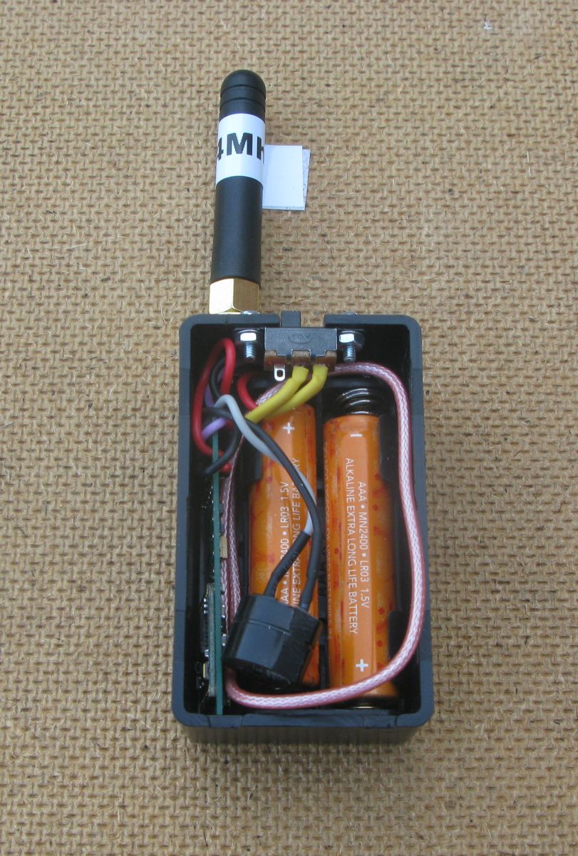
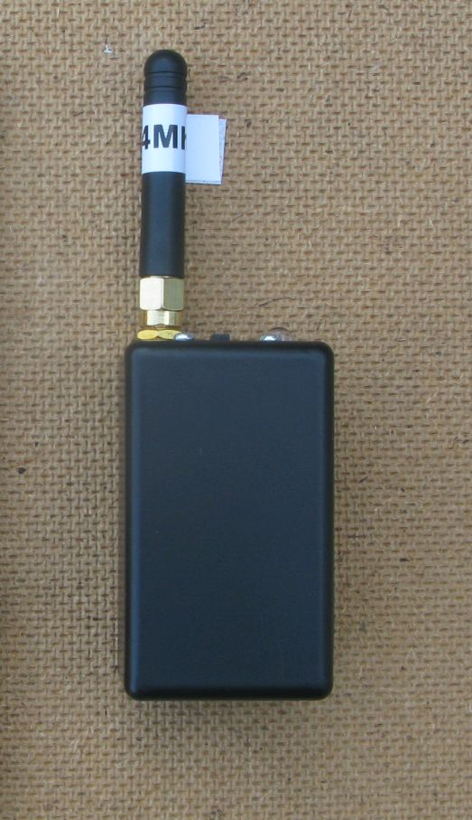
The receiver certainly works and since the antenna is on a SMA socket you could fit a bigger antenna for longer range if so needed.
Range Testing
For a basic test I loaded a program in the alarms micro controller that would send a LoRa packet every 3 seconds. I put the Alarm, which was off, in the normal position on my bike, and put the bike in the drive, then I went for a walk with the receiver. This was in an urban area with plenty of houses about. The receiver stopped working when I was 750M and several streets away from the transmitter, which is not bad for an urban area and its far enough for the cycle alarm repeater. In more open areas the range would be very much greater, many kilometres, the limiting factor here would be the curvature of the Earth which would put the transmitter and receiver out of ‘sight’ of each other.
The LoRa settings were frequency 434Mhz, spreading factor 12, bandwidth 62500hz and coding rate 4:5. The transmitter was sending a packet of 6 bytes long and the air time was 1523mS. Considering the range was more than adequate, you could most likely use shorter range LoRa settings.
The prototype circuit board had one error; the RXD and TXD for the programming interface were reversed. A decision was also made to change the optional crystal to the more common resonator type. PCBs are being ordered and will be available on Tindie in the next month or so.
Further testing
So the transmitter and receiver work well enough, although an improved receiver with a display would be good. Then the receiver could show the transmitters battery voltage and tell you what the received signal levels (RSSI and SNR) were which provide a useful indication of how close you are to going out of range.
An addition for the transmitter is a switch which the program will detect and if on instead of going back to sleep once an alarm indication has been sent the program would go into a mode whereby it sends a short packet as a beacon every few seconds. This could then be used as an indicator by the receiver that the transmitter was working and within range.
The beacon idea has been incorporated into the code (links to the code are below) and the basic receiver emits a short click when the beacon packet is received, so you know when you are in range of the alarm.
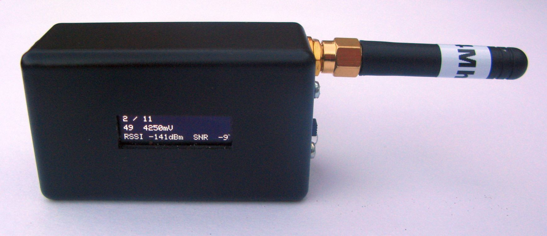
It was easy enough to put the basic receiver into a small plastic box, and whilst software wise adding a small display is easy, building the receiver with display was a bit fiddly.
However, it did just prove to be possible to fit a small 0.91” OLED in the lid, so by keeping a track of how many beacons you receive, and displaying the RSSI and SNR values on the display you have a reasonable idea as to how much within range of the alarm you are. And you even get to see what the battery voltage on the alarm transmitter is. Plus the receiver displays it’s battery voltage at switch on too.
Lilygo TBeam as receiver
The Lilygo TBEAM V1.1;
http://www.lilygo.cn/prod_view.aspx?TypeId=50060&Id=1317&FId=t3:50060:3
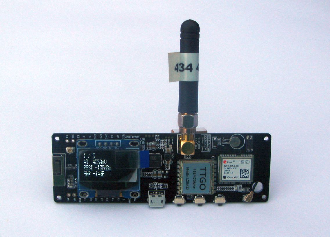
Is a ready built portable and battery powered LoRa receiver that will run the alarm receiver program, see the file 8_Lilygo_TBeam_LoRa_Receiver at the link below. The TBEAM runs from a 18650 lithium battery on the back of the board.
A 5V buzzer (which works on 3.3v) was wired to pin 15.
Future possibilities
OK, the basic transmitter and receiver works, and once the micro controller on the alarm is built, its not difficult to wire it into the alarm. However to get the size down the micro controller is built with fairly small SMT components. It would be good if the micro controller that is the alarm repeater and receiver were simpler to build.
One possibility for the transmitter (or receiver) is the Seeeduino_XIAO, which has a SAMD21 M0+ processor and has enough IO pins for driving a LoRa device.
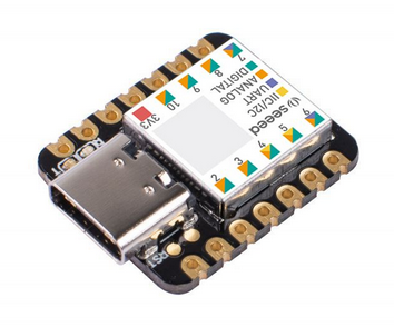
I have tested a XIAO with my own LoRa library and basic transmit and receive sketches do work. I also tried a sketch to put the XIAO into deep sleep and wakeup on external interrupt and in this mode the sleep current is 19uA, which is low enough for a good many battery applications. The sleep current increases to 20uA, when a LoRa device is added that transmits a packet on wakeup.
The XIAO has an RTC wakeup capability and that produces a deep sleep current of 5uA. If you had a LoRa application that needed to use DIO0, DIO1 and DIO2 on an RFM9X device than the XIAO would be left with 3 IO spare pins, however, all these 3 pins could be analogue, digital, one is a DAC and two of the pins could be an I2C or UART serial port. The XIAO will drive an I2C OLED display and SD card as well using standard Arduino libraries.
Another possibility for a ready made receiver is the Lilygo T-Impulse watch;
http://www.lilygo.cn/prod_view.aspx?TypeId=50054&Id=1409&FId=t3:50054:3
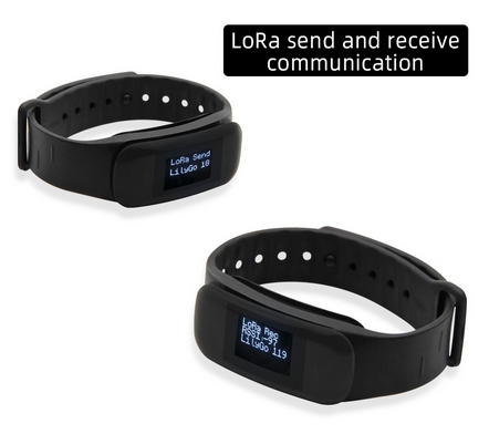
It has a display, LoRa device, vibrate alert, touch button, 9-axis motion sensor, GPS and 200mAhr battery, all built into in a device that can be worn on the wrist. Its based on the STM32L073Z processor and can be programmed with the Arduino IDE. I have tested one with my own SX12xx LoRa library and it appears to work just fine, so ‘watch’ this space there may well be an alarm receiver program for the T-Impulse along soon ……..
Examples and schematics
The programs for the application described in this article can be found on Github here;
https://github.com/StuartsProjects/Devices/tree/master/CycleAlarm